10 bit rotary magnetic encoder (AS5040)
| AS5040 | |
|---|---|
| An implementation of the AS5040 for keeping track of spindle position for the NASA Tensegrity senior design project of 2012Template:InfoboxtEntry | |
| Type | Magnetic |
| Manufacture | Austria Microsystems (ams) |
| Model | AS5040 |
| Resolution | 10 bit |
| Modes | *Absolute *Incremental *PWM |
| Interfaces | *SSI *PWM *PWM |
| Max RPM | 30,000 rpm |
This page provides detailed information on an implementation of the AS5040 which is a surface mount magnetic encoder capable of 10 bit resolution (~.35 deg). It's small footprint, contactless design made it an ideal choice for the NASA Tensegrity senior design team of 2012. There are several ways to interface with the device, but the methods here focus on absolute positioning using SSI.
These devices also come in a linear encoder flavor, and a 3D positioning sensor. See:
- http://www.ams.com/eng/Products/Magnetic-Position-Sensors/Linear-Incremental-Magnetic-Position-Sensors
- http://www.ams.com/eng/Products/Magnetic-Position-Sensors/Linear-Incremental-Magnetic-Position-Sensors
Features[1][edit | edit source]
- Contactless high resolution encoding over a full turn of 360°
- Flexible system due to user programmable incremental output modes:
- 10-, 9-, 8- or 7-bit user programmable resolution
- Quadrature A/B and index output signal
- Single channel output and direction indication
- U-V-W commutation signals for brushless DC motors
- Absolute angular position mode:
- 10-bit resolution providing 1024 absolute positions per 360° (step size ~ 0.35°)
- Synchronous serial interface (SSI) output for absolute position data
- Pulse width modulated (PWM) output, duty cycle proportional to angle
- User programmable zero and index position
- Failure detection mode for magnet placement monitoring
- Rotational speeds up to 30,000rpm (incremental output)
- Push button functionality detects movement of magnet in Z-axis
- 2 supply voltages: 3.3V or 5.0V
- Wide temperature range: -40°C to 125°C
- SSOP-16 package: 5.3mm x 6.2mm
- World’s smallest multiple output rotary position sensor
- Tolerant to magnetic source misalignment
- Failure detection feature
- Complete system-on-chip:
- Flexible system solution provides absolute, incremental and PWM digital outputs simultaneously
- Minimum number of external components needed
- Serial read-out of multiple AS5040 devices using daisy chain mode feature
- Ideal for applications in harsh environments due to contactless position sensing
Overview[edit | edit source]
Encoder technology[edit | edit source]
There are many types of encoders, but this page is in reference to position encoders. Encoders provide positional information (linear and angular) which can be used for velocity and acceleration. Various types of encoders exist including:
- Mechanical
- optical
- Magnetic
- Capacitive
Outputs that encoders generate include:
- voltage
- PWM
- binary
- data (SSI, etc.)
For a more in depth look at encoders, see:
Typical Applications[edit | edit source]
- motors
- shafts
- callipers
- speedometers
- Digital read out (DRO) on a mill or lathe
- robotics
- position, velocity, acceleration measurements
Specifics/details[edit | edit source]
The application of the AS5040 presented on this page allows for 8 absolute position encoders to be daisy chained together using SSI
Block diagram[edit | edit source]
Schematic[edit | edit source]
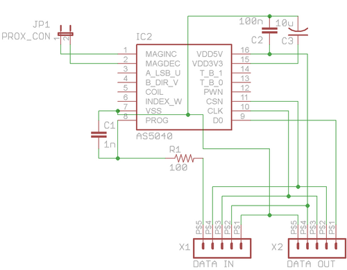
Pins (of the AS5040) 1-MAGINC and 2-MAGDEC are connected to a two pin header that can determine if the position of the magnet with respect to the AS5040 is decreasing or increasing. See datasheet for more info. These pins can be useful for using the device as a proximity switch, or for general purpose diagnostics.
Pin 7-VSS is ground
Pin 8-PROG is the data input for daisy chain mode. R1 and C1 are an RC filter required for daisy chain mode.
Pins 9-DO, 10-CLK, and 11-CSN are data out, serial clock, and chip select respectively.
Pin 15-VDD3V3 is the 3.3V V+ and is not used and is connected to ground through a capacitor (required). Pin 16-VDD5V is the 5V V+ and is also connected to ground through a capacitor.
Connector 1-Data in (X1) provides power, SSI interface, and programming interface and is connected to an Arduino (or similar device) or the previous encoder. The pin out is 1-ground, 2-5V, 3-serial clock, 4-chip select, 5-data in.
X2-Data out provides power, SSI interface and programming interface to the next encoder in the daisy chain, or provides the data in to an Arduino.
Note: This is only one implementation (Absolute, SSI) of the AS5040, the chip has many more outputs and capabilities, see data sheet for more information.
PCB layout[edit | edit source]
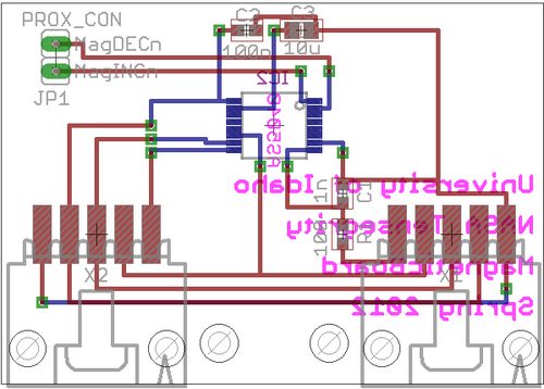
Pretty simple board, worked well.
Recommendations for improvement:
- Use of ground plane
- Could probably use much smaller connectors and cut the board in half
- C2 and C3 should ideally by closer V5 and V3
- Could probably move all components to one side if necessary
Mechanical design[edit | edit source]
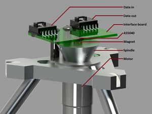
The board was counter-levered over the spindle of the motor using plastic standoffs and machine screws through the two mounting holes (between the two Molex connectors). This ultimately worked, but there were some issues with alignment. This could be improved greatly.
[[[Link title][[File:Link title ---- Insert non-formatted text here<math>Insert formula here</math>]]]]===Code=== A complete library was written in c for the Arduino called AS5040. It requires the following additional libraries:
- digitalWriteFast
- wiring
- slavesCommunication
The library is broken consists of the files:
- AS5040.h - the header file which contains the definitions of all of the callable functions, and startup variables
- AS5040.cpp - the code which defines the callable functions in the header file, and all supporting functions
- keywords.txt - allows callable functions to be recognized by the Arduino IDE for syntax highlighting
Usage[edit | edit source]
Placement[edit | edit source]
Wiring[edit | edit source]
API[edit | edit source]
sendInstruction getPosition getStatus int getAngle getQuickStatus getDirection printData
References[edit | edit source]


