Advanced Multi-rotor Drone
| [[File:|300px|center|alt=]] | |
| Example | |
| Sponsors | Peter Baran
|
| Team Name | Two birds and one drone(TBOD) |
| Duration | Fall 2018 - Spring 2019 |
| Faculty Adviser | Dr. Feng Li
|
| Client | Peter Baran
|
| Team Members |
|
Design Goal[edit | edit source]
The main project objective is to understand the ground-up multi-rotor drone design. It will include the electro-mechanical design and construction of the airframe, the design and construction of electrical/electronic circuitry to implement the control system that allows the drone to fly, and the design and construction of tools to aid in the process. The control system design will be implemented in an FPGA. A large portion of this project is developing tools to pass on to future teams. This includes various customized tools and methodologies for the development process.
Project learning[edit | edit source]
FPGAS: Field Programmable Gate Arrays are devices that are based on around a matrix of configurable logic blocks (CLBs) which have programmable connections. We can use this property to monitor and respond to all of our sensors simultaneously, allowing extremely fast response time.
ESCs:In terms of individual components to go on the boards, we needed MOSFETs to drive the motors, current switching ICs to drive the MOSFETS, comparators to measure back EMF, and an assortment of resistors, capacitors, and diodes. A brushless DC motor to turns as the result of switching the flow of current through its three coils. At any given time, one coil is connected to the supply voltage, another coil is connected to ground, and the other coil is connected to high impedance. Depending on which coil is in which state, the motor will align to a certain position. By switching the states of the coils, the motor can be operating in a similar way to a stepper motor. The motor will have an optimal speed depending on the supply voltage so state transitions need to occur at specific times. Additionally, a PWM signal can be used to modulate the source voltage and the resulting optimal motor speed. Brushless DC motors are designed so that when the coil connected to high impedance passes a magnet on the stator, it is time to switch to the next state. This time can be determined by sensing the back EMF on that coil and comparing it to a virtual neutral.
Motor characterization[edit | edit source]
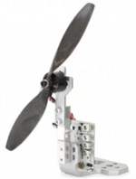
While researching potential motors and propellers for our drone, it became evident that larger propellers are more efficient than smaller propellers in producing thrust. We also learned that propellor material and design is also important. The strength, as well as the angle of attack of a given propellor, determine its efficiency and its weight to thrust ratio. This led to our choice to use Carbon Fiber blades for our rotors.
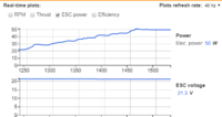
According to the data from the real-time plotting, each motor with this specific propeller produces a reasonable amount of lift which is Approximately 380g.
|
|
|
|
Mechanical Design[edit | edit source]
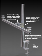
There are the early mechanical modelings of our final deliverables.
Final deliveriables[edit | edit source]
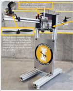
There are final Mechanical and Electrical Engineering deliverables.Team Members[edit | edit source]
| Picture | Bio | Discipline |
|---|---|---|
Caleb Smith:
I'm a senior in Mechanical Engineering from Boise, ID. |
ME | |
Makynzie Zimmer :
I’m a senior in mechanical engineering here at UI and am from Boise, ID. |
ME | |
Preston Stephens:
I am a senior from Coeur d'Alene, Idaho focusing on digital design. |
CompE | |
Matthew Shryock:
I'm a senior in Electrical Engineering, and I'm from Coeur d'Alene, Idaho. |
EE | |
Pengqiang Ge:
I am a senior from China. |
EE
|
Design Validation[edit | edit source]
| Requirement | Test | Test subject | Target Date | Result | recommendation |
|---|---|---|---|---|---|
| Prototype Motors need to be able to produce enough lift for flight and control | Measure the thrust produced by the motors with a motor test rig | prototype Motors and Rotors | 10/17/2018 | Motors produced a reasonable amount of lift. Approximately 380g. | N/A |
| Finished Product may not exceed 6 feet in any direction | Measure finished product | Fully functional final product | 4/26/2019 | Yes | N/A |
| The helium balloon will displace at least 1/3 of the total drone weight. | Lift of the balloon and drone weight will both be measured using the wheatstone bridge in the drone lab | Fully functional prototype | 4/26/2019 | Yes | N/A |
| Must account for variability in BC consistency and texture | Manually, visually inspect BC for clumping and inconsistencies in texture; should be no particles larger than 0.25 inches | Functional prototype | 3/21/2019 | Yes | N/A |
| Be able to control its flying direction by using programming and controller | Set product in an uncontrolled environment outside | Fully functionnal final product | 4/26/2019 | Yes | N/A |
| Produce a balloon for prototype that has approx 280 g of lift | Measure the lift of the balloon using the wheatstone bridge assembly in the drone labes | Fully functioning prototype balloon | 4/26/2019 | Yes | N/A |
| Produce an Arduino based flight controller | Confirm that the controller produces stable flight and responds to user commands | Fully functioning prototype product balloon | 4/26/2019 | Yes | N/A |
| Produce a FPGA based flight controller | Confirm that the controller produces stable flight and responds to user commands and verify use | Fully functioning final product | 4/26/2019 | Yes | N/A |
| Be able to perform the grid path and return to home point | Field testing | Fully functioning final product | N/A | N/A | N/A |
Flow chart for control system[edit | edit source]
File:FPGA Flow Chart.pdfAdditional Documentation[edit | edit source]
Meeting Minutes
9/20 Meeting Minutes
9/28 Meeting Minutes
10/04 Meeting Minutes
11/01 Meeting Minutes
11/08 Meeting Minutes
12/13 Meeting Minutes
3/1 Meeting Minutes
3/22 Meeting Minutes
3/23 Meeting Minutes
4/5 Meeting Minutes
4/12 Meeting Minutes
4/19 Meeting Minutes
4/20 Meeting Minutes
4/22 Meeting Minutes
Design EXPO Materials
