Aerodynamic Study of Bulk Commodity Tractor Trailers
| Western Trailers | |
| Team Name | Trailer Park Boys |
| Sponsors | |
| Team Members |
|
| Duration | Fall 2017 - Spring 2018 |
| Faculty Advisors | Dr. Steven Beyerlein |
| Mentor | Sarah Willis |
Our project goal is to test aerodynamic features of two existing tractor trailers and measure the reduction in fuel consumption as well as emissions. This will be accomplished by studying and comparing the drag coefficients of each design. Our scaled-down models will be created with 3D-printing and laser cutting technology.
Problem Definition[edit | edit source]
Semi-trucks are used all over the world for transporting goods. They provide easy and affordable methods to keep economies running. The downside is that semi-trucks produce a lot of carbon-dioxide pollution from their exhaust. If the trailers they tow are improved aerodynamically, that carbon-dioxide production can be minimized. The Western Trailer Company, headquartered in Boise, ID, has a multitude of tractor trailers that have different aerodynamic characteristics. The Trailer Park Boys are tasked with testing and simulating these trailers in various configurations so improvements can be made to meet new tractor trailer requirements that will be implemented in 2018.
Design Goals & Deliverables[edit | edit source]
At the end of the project, the client will receive:
- Scale models of selected Western Trailer products suitable for testing in the University of Idaho's Mechanical Engineering Wind Tunnel
- Wind Tunnel data on aerodynamic drag associated with different scale models at different wind speeds
- Methodology for translating changes in scale model drag coefficients to changes in fuel efficiency and emissions for full-size trailers (following appropriate federal guidelines)
- Quantify changes in trailer performance associated with changes in trailer geometry for specific trailer models
- Final design report that documents the team’s model development and testing process
Model Design[edit | edit source]
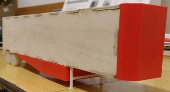
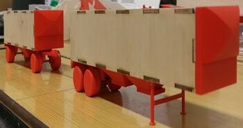
At the start of the project, our team was first tasked with creating scaled-down models of various Western Trailer products so that we could use the wind tunnel. The wind tunnel test section is 18" x 18", and the blockage ratio cannot exceed 10%. We decided to base our entire scaling system off our model height of exactly 3". This resulted in a scaling factor of 1:38.33 and an overall blockage ratio of 2.47%. The resulting length and width of the 48-foot trailer model was 15.018" and 2.671", respectively. The A-Train models also followed this scaling factor, resulting in a height of 2.039" and a width of 2.560". The lead trailer is 10.106" long and the pup trailer is 7.915" long.
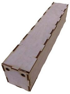
Five panels were cut out of 1/8" birch wood on the laser cutter at the University of Idaho. The five panels included the front, sides, top, and bottom panels of the trailer models. An intuitive tooth design was used to ensure correct alignment of all the panels on each model. Wood glue was placed on the edge of each tooth when the panels were assembled.
| Feature Label | Description |
|---|---|
| 1 | Magnets |
| 2 | Force Balance Attachment |
| 3 | Front-end Attachment |
| 4 | Under-Carriage Attachment |
| 5 | A-Train Tongue |
| 6 | Landing Gear |
| 7 | Wood Panels |
| 8 | Trailer Axles |
Trailer features, such as a nose cone or hopper bin, were 3D-printed with PLA plastic on a 3D Sindoh printer. These features needed to be attached to our trailers for testing, so we decided to use magnets. With each trailer feature, a recessed region would be created in the part for a magnet to be glued in. Inside the trailer, magnets were glued on to the wooden panels in precise locations to ensure correct placement of all features.
Testing Matrix[edit | edit source]
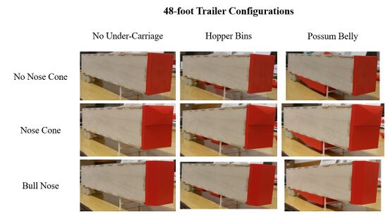
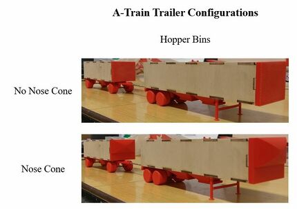
Before we put our models in the wind tunnel for testing, we organized a test matrix for both models to stay organized when testing. The 48-foot trailer had a total of nine possible configurations, and the A-Train trailer had a total of ten possible configurations, resulting in 19 total tests.
| Full-size Tongue Length | Model Tongue Length |
|---|---|
| 7-foot 1-inch | 4.47 inches |
| 9-foot 7-inch | 5.26 inches |
| 14-foot 1-inch | 6.67 inches |
| 16-foot 7-inch | 7.45 inches |
| 21-foot 7-inch | 9.02 inches |
The testing matrix for the 48 foot trailer configuration is located on the left, while the testing matrix for the A-Train configuration is located on the right. The spacing between the lead and pup trailer in the A-Train configuration will also vary. The table above gives the five different lengths that were tested.
Data Processing[edit | edit source]
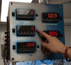
Data acquired from the force balance in the wind tunnel was recorded in Microsoft Excel and then processed in Matlab. The data was processed and analyzed as follows:
1) Acquire drag force data from the electronic displays that are connected to a force balance within the wind tunnel.
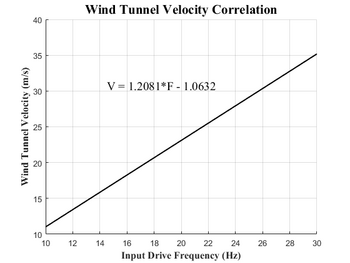
2) Correlate the wind speeds to the frequency of the fan driver input on the wind tunnel.
3) Values such as density and projected cross-sectional area are determined and held constant for the entire analysis of each model.
4) Calculate the drag coefficient of each model configuration.
5) Create plots that compares the drag coefficients of similar models, such as the 48-foot trailer with different front-end attachments.
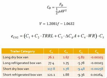
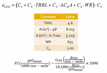
6) Determine the constants (C1 through C5) for each model. For our testing, the same constants are used for every model. According to official documentation, a trailer is considered long if it is over 50 feet. The longest model we have is a 48-foot dry box van trailer. The Tire Rolling Resistance Level (TRRL) and Weight Reduction (WR) were taken from an example from Cornell Law School that discussed the details of the new regulations.
7) Calculate the emissions output in units of grams of CO2 per ton-mile.
8) Calculate the fuel consumption rate per 1000 ton-miles is calculated.
Testing Results[edit | edit source]
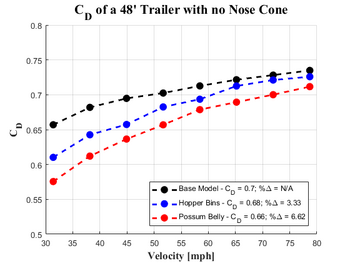
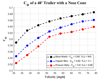
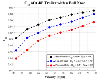
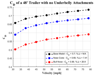
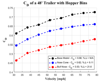
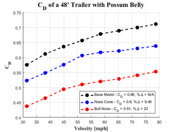
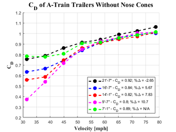
Wind Tunnel speeds were ran from approximately 14 m/s (~30 mph) to about 35 m/s (~78 mph) in increments of roughly 2.5 m/s (~7 mph). This range of speeds showed relatively linear trends of the coefficient of drag during our early testing sessions. Below are some plots that contain coefficient of drag against wind velocity for both the 48-foot trailer model and the A-Train trailer model. The bull nose provided the largest reduction in drag force for the front-end configurations, and the possum belly gave the lowest drag coefficients for the under-carriage configurations.
48-Foot Trailer Results[edit | edit source]
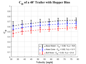
We saw that all attachments reduced aerodynamic drag with respect to the corresponding base model. The three plots in the table below each compare the coefficients of drag on the 48-foot trailer model with the three different under-carriage configurations (no under-carriage, hopper bins, and a possum belly) while keeping the front-end configuration constant (without a nose cone, with a nose cone, and a bull nose).
We also compared the coefficients of drag on the 48-foot trailer model with the three different front-end configurations while keeping the under-carriage configurations constant.
Changing the front-end configuration of the trailer from a flat-face to either a nose cone or a bull nose provided a much larger decrease in the drag coefficient versus a change in the under-carriage configuration, but changing the under-carriage did provide some decrease in the drag coefficient.
A-Train Trailer Results[edit | edit source]
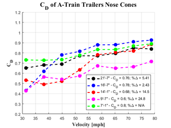
For the A-Train Trailers, we saw that adding a nose cone to both the lead and pup trailers provided a significant decrease in the drag coefficient across all tongue lengths. The tests that were ran without a nose cone all followed closely to a common linear trend at higher speeds, whereas the tests with a nose cone saw larger deviations from one another. We are unsure as to why the nose cone tests saw a wider spread of data between the tongue lengths, but we assume its due to either added turbulence from the shape of the nose cones or slight sensor errors in the wind tunnel.
After we plotted the drag coefficients (with a nose cone) versus wind velocity, we observed a sweet spot for a tongue length, which is right around the 9'-7" length. This configuration saw the largest percent-decrease in the drag coefficient with respect to the shortest length configuration (with a nose cone) at nearly 25%.
Error Analysis[edit | edit source]
Properly reported data must include an error analysis. We performed a root sum square (RSS) method on all of our aerodynamic data to see whether or not a definite decrease could be accepted. In most data analyses, the possible upper limit of one configuration was well below the possible lower limit of the configuration that had a higher average drag coefficient (see the images below). At lower speeds, the upper and lower error limits mixed, so it is hard to definitely say a reduction in drag coefficient occurred, but at higher speeds, the upper and lower error limits of different models diverged.
Project Learning[edit | edit source]
Wind Tunnel[edit | edit source]
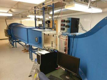
This project was the first time our group got to use the wind tunnel extensively. Graduate students gave us an introduction on how to operate the wind tunnel on our first day of testing, but after that, we operated the wind tunnel on our own. We did learn that the frequency drive input of the fan motor is not exactly a one-to-one ratio with the wind tunnel speed in meters per second, so we had to create our own linear correlation between the frequency drive input and the wind tunnel velocity.
Model Design[edit | edit source]
When testing scale models, geometric similitude is very important. The ratio of model length to full-size length must be identical to the ratio of model width to actual width, and so on with other dimensions. Our initial model design involved 3D printing the entire trailer as one piece, with two structural support within the trailer. One of these support structures would had a hole for the for balance to rest in so we could acquire aerodynamic drag data. The main issue with this model is that it was about 15 inches long, and the 3D printers we used could only print up to eight inches. Another issue we encountered was attaching the different configurations for model testing, i.e nose cones or hopper bins. If we had printed out this trailer model as one piece, it would have been very difficult to place the magnets inside the trailer for easy attachment of the configurations. We ultimately decided that laser cutting trailer panels for our models was a more efficient method of modeling the trailers.
Manufacturing[edit | edit source]
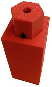
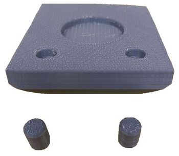
3D printing configuration parts is an excellent solution to creating various features of our models. We used a 3D Sindoh printer with extremely fine settings to reduce the skin friction drag of all 3D printed parts as much as possible. Some parts had to have extra internal features to be successfully printed. This is mainly due to the fact that the 3D printer can only print in an 8" x 8" x 8" space. The upper left-hand image shows a part that needed to be printed in two sections. The upper right-hand image shows tabs that were needed to be designed into the part. Some parts also needed extra material for set screw locations, such as the tongue piece for the A-Train trailers.
Conclusions & Recommendations[edit | edit source]
Our data analysis showed that:
- For the 48 foot tractor trailer, we found the best option to be achieved from using a bull nose and possum belly configuration. This combination was found to disrupt the airflow the least with a drag coefficient of 0.506.
- For the A-Train trailer setup, we found the best option to be achieved from using a nose cone and an extended tongue length of 9'7" a bull nose and possum belly configuration. This combination produced a drag coefficient of 0.601.
We recommend a skin friction drag analysis for our models, as the balsa wood used to construct them has a different texture than typical sheet metal used to construct full-size trailers. We are unsure how significant the skin friction drag played in our aerodynamic drag tests, but it would be good to ensure that is does not significantly effect the data. We also recommend an analysis with a semi-truck in front of the trailers, as we expected the nose cone front-end configuration on the 48-foot trailer to have a lower drag coefficient than a bull nose configuration. This is because the nose cone attachments have an underside to the rounded top, creating a possible pocket of stagnant, high-pressure air. If a semi-truck were in front of the trailers, this area would be shrouded by the truck and potentially decreasing the aerodynamic drag.
Team Members[edit | edit source]
| Member | Photo | Biography | Discipline |
|---|---|---|---|
| Brandon Hilliard |
Brandon Hilliard is a Mechanical Engineering Senior at the University of Idaho. His interest in mechanical things began when he was working on cars with his father. Originally, he was planning on becoming an automotive technician, but he also wanted to learn how to design mechanical systems, such as an automobile, so he chose to become a mechanical engineer. His interests in the mechanical engineering field include heat transfer, fluid dynamics, and mechanical design. Outside of school, he enjoys playing basketball, playing guitar, cooking, and drag racing. |
Mechanical Engineering | |
| Liam Johnson |
Liam Johnson is a Mechanical Engineering Senior at the University of Idaho. He has citizenship for both the United States and Canada. This allowed him to obtain a mechanical engineering internship last summer in Newfoundland, Canada. His interests are in design and manufacturing optimization. His current goal is to work in the industry for a few years before returning to school to specialize in a field of interest. |
Mechanical Engineering | |
| Jacob Frost |
Jacob Frost is a Mechanical Engineering Senior at the University of Idaho. His interests are Power, Energy, and Efficiency. He was raised in a small farming community and still to this day is interested in Powerful machinery like tractors. Throughout his undergraduate studies he has learned that energy comes in many forms and always to apply the term “work smarter not harder”. |
Mechanical Engineering |
