Autoclave Upgrade for Corrosion Fatigue Testing
| Team Name | Autoclave Experts |
| Duration | Summer 2018 - Fall 2018 |
| Faculty Adviser |
|
| Mentor |
|
| Client |
|
| Team Members |
|
Expand the University of Idaho’s current fatigue testing capabilities to include an autoclave load frame that supports testing of metals as well as operating conditions experienced in nuclear power plants.
Problem Definition[edit | edit source]
Background[edit | edit source]
| The objective of this project is to expand the University of Idaho’s current fatigue testing capabilities to include an autoclave load frame for use in fatigue testing of materials with a focus in metals to be used in nuclear power plants. Currently, no system is on hand to accomplish the fatigue testing environment desired by Dr. Stephens. Currently, there are two load frames with furnaces capable of reaching temperatures up to 700°F, but neither of them have an airtight seal installed. The proposed new system will be able to tolerate temperatures of up to 750°F and 3000 psi while delivering 10,000 lbs of force.
Currently, the lab’s load frames can do fatigue creep testing in an air environment. Fatigue tests slowly apply a tensile load which tears apart a specifically shaped sample over an extended period. The growth rate of the crack is of interest because it is used to predict the lifespan of the material in other applications. The proposed system will perform the same style of tests but will be capable of testing the response of the material to corrosive and pressurized environments. |
|
Deliverables[edit | edit source]
The scope of this project includes designing/purchasing all of the components for the fatigue testing apparatus, assembling it, and testing it for proper usability as defined in the following deliverables.
Initial Client Meeting & Expectations
The initial client meeting was conducted on June 14th, 2018. Dr. Stephens and Nicholas Schaber prepared the following list of Primary Objectives for the project.
- Load Frame Upgrades
- Loading system (motor/drive/gearbox, rated to ≈10 kips)
- Load cell (coinciding with applied loads)
- Load cell calibrated in line with seal
- Load train displacement measurement (LVDT)
- Extension rates up to 0.05 mm/s
- Lid lifting/holding device
- Load Control and Measurement
- Feedback control loop (load controlled)
- User interface for load frame
- Programmable loading waveforms including:
- Variable strain rate
- Fatigue (cyclic loading, variable frequencies)
- Creep-fatigue (variable hold time and set loading)
- Constant load
- Crack measurement/monitoring (DCPD)
- User interface over/under warnings (temp, pressure, load)
- Autoclave Upgrades
- High temperature/pressure dynamic seal
- Lid modifications
- Loading rod
- Internal load support
- Isolated through-lid fittings for DCPD wires
- Operating temperature of 400°C (≈750°F)
- Operating pressure of 20MPa (≈3000psi)
Specifications
Utilizing the above list of deliverables from the client, a refined list of specifications has been produced. The full document is available in the "Additional Documentation" section.
The following is a shortened list of our most important specifications and deliverables.
- Functionality
- UI should emulate that of other load frame currently in use by U of I
- Emergency stop function digitally via LabView UI and mechanically via physical “button”
- Extension rates up to 0.05mm/s during testing
- The loading system (motor/drive/gearbox) design shall be able to deliver a maximum load of at least 10,000 pounds.
- Design shall be able to accommodate standard sized test specimens
- All components shall have 99% reliability. A DFMEA will take this into account
- Programmable loading waveforms including:
- Variable strain rate
- Fatigue (cyclic loading, variable frequencies)
- Creep fatigue (variable hold time and set loading)
- Constant load
- Crack measurement/monitoring via DCPD
- Evironmental Requirements
- All internal autoclave components shall be designed to withstand temperatures of at least 300° C
- All internal autoclave components and seals shall be designed to withstand pressures of at least 28MPa (4000 psi)
- All internal autoclave components and seals shall be designed to withstand the same corrosives as the 316H stainless steel that the autoclave is made of
Acronyms used in this text
- UI: User Interface
- LVDT: Linear Variable Differential Transformer
- DCPD: Direct Current Potential Drop
Project Learning[edit | edit source]
| The autoclave load frame system being developed has many components, but the two requiring the most research and consideration are the Dynamic Seal and the Actuation System. |
Dynamic Seal[edit | edit source]
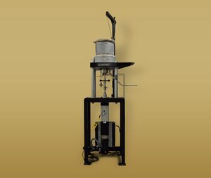
With the design shown in Figure 1, a rod is moved linearly through the top of the autoclave pressure chamber. This requires a strong, Dynamic Seal to handle the movement of the rod while containing the required maximum temperature, pressure, and corrosive environment.
One of the seals considered is a Stuffing Box. According to Wikipedia, a stuffing box is an assembly which is used to house a gland seal. It is used to prevent leakage of fluid, such as water or steam, between sliding or turning parts of machine elements.
|
 Stuffing Box Image courtesy of https://www.brighthubengineering.com/naval-architecture/43359-what-is-a-stuffing-box/#imgn_0 |
Another option considered is a spring seal, which is a shaft seal with a Garter Spring contained within the seal to provide compression around the shaft and prevent leakage.
|
 Spring Seal The original uploader was Jean-Jacques MILAN at French Wikipedia. https://commons.wikimedia.org/w/index.php?curid=4860492 |
The next seal considered is a Metal Bellows. Wikipedia defines metal bellows as elastic vessels that can be compressed when pressure is applied to the outside of the vessel, or extended under vacuum. When the pressure or vacuum is released, the bellows will return to its original shape (provided the material has not been stressed past its yield strength).
|
 Metal Bellows By Корниенко Виктор - Self-photographed, CC BY-SA 3.0, https://commons.wikimedia.org/w/index.php?curid=8058215 |
Actuation System[edit | edit source]
Referring again to Figure 1, an Actuator System is needed to raise and lower the gripper arm attached to the test specimen. This system needs to be robust enough to provide the test loads required for fatigue testing of the specimen.
Hydraulic
- Advantages
- Capable of delivering faster load frequencies (15-60 Hz)
- Higher max speed ramp up rate and turnaround rate
- Significantly less expensive
- More commonly available components
- Disadvantages
- Requires an external pump and cooling
- Larger amount of individual components
Electric
- Advantages
- Simpler system (less individual components)
- Smaller footprint in lab
- Disadvantages
- More expensive overall
- Slower load frequency capabilities (~1 Hz)
- Lower Lifetime
Decision Matrix
In order to make an informed decision on the type of actuation system we needed to purchase, a decision matrix was created. The categories, weights, and values of the matrix were all discussed and agreed upon by the team as a whole.

Using this decision matrix, we were able to easily settle on a hydraulic actuation system as our best candidate for this project.
Final Design[edit | edit source]
| Systems | |
|---|---|
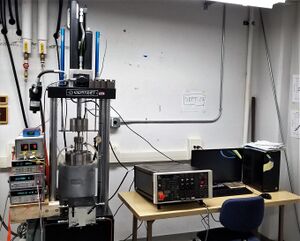
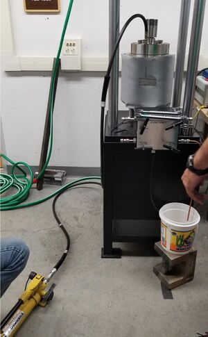
| Main Assembly Pictured here are the primary components of our prototype system. You will notice the hydraulic components mounted to the top of the autoclave framework on the top left of the photo, the dynamic seal mounted to the lid of the autoclave, the MTS Controller sitting on the table in the center, and finally the desktop computer running our Labview data collection software on the right. |
|
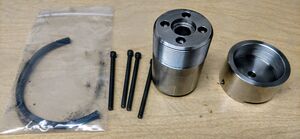
| Dynamic Seal After a significant amount of discussion and consideration of the benefits of each of the seals described in the Project Learning section above, it was decided to take advantage of both the high-temperature/ high-pressure qualities of the stuffing box seal, and the low friction of the spring seal. For our design, the load rod will pass through a stuffing box gland seal. This seal will be stuffed with a special extreme temperature and pressure packing material. This packing is both impregnated with graphite and has Inconel wire embedded into it. This seal will take the brunt of the high pressure and temperature from the autoclave. Behind the stuffing box is a water jacket. This water jacket will cool the load rod and prevent heat creep from affecting the load cell above. The jacket will be sealed above by a spring seal, which does not need to have nearly as high of a temperature rating as the stuffing box seal. In the event of the stuffing box seal being breached, the high temperature/pressure fluid escaping from the autoclave will be caught in the water jacket and sent out of the return line. The spring seal is rated to hold the pressure that it would experience in this event. |
|
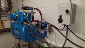
| Pump System The pump chosen to run our hydraulics needed to be located in a small room attached to the laboratory. This room already contained two pumps running the two load frames in our lab, and these were oversized as they were freely available at the time. This meant a limited amount of space was available for our team to work with, so we opted to purchase a smaller, 1.5 gpm pump that was still capable of providing the flow rate we needed. We mounted it to the cinderblock wall with a frame we designed and built to keep it up and out of the way from the other equipment in the room. Additionally, a small heat exchanger was sized and mounted to cool the hydraulic fluid, which will be flowing continuously when a test is running. |
|
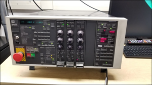
| Controller Originally, the plan was to use Labview connected to a National Instruments DAQ to control the hydraulics. After 3-4 weeks of troubleshooting and brainstorming, it was determined that our version of Labview, coupled with the capabilities of our DAQ, was insufficient to provide the computing speed needed to run our hydraulics. Because of time constraints, we opted to use a spare analog controller that the lab already had access to. This controller, made by MTS in 1972, is identical to one already being used on another load frame in the same lab. This fact enabled us to quickly adapt our system to use the MTS controller and begin testing our hydraulics. The MTS controller is capable of meeting all of our programming requirements and seems to function superbly for our application. |
|
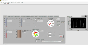
| Labview Data Collection While Labview was abandoned as a control solution, it is still being used for data collection. Data is collected on:
|
Validation[edit | edit source]
| System Validation | |
|---|---|
| Validation of key systems was accomplished throughout the Fall semester, once our systems began to come together. Tests were performed on the hydraulics, the dynamic seal, the electronics, and all other critical systems. For details on the validation tests that were used, please refer to: File:2018 AutoclaveExperts ValidationPlan.pdf |
Team Members[edit | edit source]
| Tyler Jones
Major: Mechanical Engineering
| |
| Titus Hansen
Major: Mechanical Engineering
| |
| Bahram Sobbi
Major: Mechanical Engineering
| |
| Larry Schwab
Major: Mechanical Engineering
| |
| Kevin Brewer
Major: Mechanical Engineering
|
Additional Documentation[edit | edit source]
Presentations
File:2018 AutoclaveExperts DesignReviewPresentation.pdf
File:2018_AutoclaveExperts_Snapshot2Storyboard.pdf
File:2018_AutoclaveExperts_Snapshot_3_Storyboard.pdf
File:2018_AutoclaveExperts_Snapshot_4.pdf
Documents
Project Schedule
File:2018_AutoclaveExperts_GanttChart12-7-18R5.pdf
Meeting Minutes
File:2018 AutoclaveExperts MeetingMinutes.pdf
Product Requirements
File:2018_AutoclaveExperts_ProductRequirementsR3.pdf
Client Interview
File:2018_AutoclaveExperts_QuestionsForClient.pdf
Team Contract
