Autonomous COTS Bots
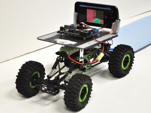
| Android-powered COTS Bot attempting to navigate the blue-colored path in the background. The phone screen shows what the "brain" sees as the correct path (green) as opposed to background information (red). | |
| Sponsors | |
| Team Name | AutoCOTS |
| Duration | Spring 2015 |
| Faculty Advisors | |
| Students |
|
| Past Students |
|
The goal of this project is to use the Commercial-Off-The-Shelf (COTS) Bots platform and add inter-robot communication and autonomy to perform cooperative tasks.
The COTS requirements for our robots are that they are:
- Affordable (<$500)
- Easy and quick to assemble (e.g. <30 minutes, no soldering)
- Computationally powerful
- Programmable using modern languages and fully featured IDEs.
- Durable
Most of the people involved in the COTS Bots project have computer science backgrounds and as such, the focus of the COTS Bots project is on the software element of the project rather than the hardware element. The hardware for the bots should then be simple to build and maintain while still allowing for computationally powerful software.
Design Task
A considerable amount of previous work has gone into the designing, building and evaluation of multiple robot designs. The most successful design so far has consisted of three basic components:
- The "brains" -- typically a smartphone or netbook.
- The "body" -- the platform from an RC car, tank, truck, or other vehicle.
- The "spinal cord" -- a microcontroller or motor controller, such as made by Arduino or Phidgets.
The brain controls the robot, the body moves the robot and the spinal cord acts as the communication between the brain and the body.
The primary sensors for the robots are contained in the "brain" and include, in the case of a smartphone, one or two cameras, a microphone, accelerometers, tilt sensors and GPS transceivers. In addition, other sensors, such as bump sensors and infrared or ultrasonic range detectors, can be plugged into the "spinal cord" as well.
The "brain" also comes with easy to access output devices such as speakers and screens.
Problem Statement
The current COTS Bots can perform tasks individually, but the current communications methods between robots for coordinated tasks have limitations. For example, the robots have been trained to follow one another by using image-recognition of a particular shape that is mounted to the robots. Typically, a colored foam sphere is attached to a rod which is then attached to a robot. By chaining spheres of different colors together, a train of robots could be formed -- each robot would follow a specific color and then the lead robot could be tasked with following a given path or could even be controlled via remote control (in fact the lead vehicle, if controlled remotely, would not even need to be a robot but just an RC vehicle). The robots could also be connected using a wireless access point -- the "brain" of each robot typically has a WiFi device that can communicate over the 802.11 wireless standard. The range of WiFi however is rather limited and is easily susceptible to electrical interference.
Design Goals
Our project goal is then to find a viable way for the robots to communicate with each other that overcomes limitations such as a low range and electrical interference. So our primary goal is to adopt a physical later and a transport networking standard. We will need to design and develop a protocol for managing all of the robots on our network as well that operates on this networking protocol.
Our main goals for the networking protocol are:
- Simplicity for the end user
- Small Packet Size
- Extensibility
- Flexibility
- Reliability
Detailed Specifications
The primary requirements of the protocol are as follows:
| General Requirement | Specific Requirement | Target Values |
|---|---|---|
| Speed | The protocol should have a small enough packet size that low power MCUs can forward or parse it quickly. | The packet size should be less than less than 80 bytes excluding user data. |
| Ease of Use | The protocol should be easy to use for the end user. | The protocol should be abstracted away from the user so that data is packaged and unpacked without knowing how the protocol itself works. |
| Validity | The protocol should produce the same output given the same input of user data. | The protocol should use well defined standards for packing and unpacking user data to make sure that the output is the same as the input. |
| Stability | The protocol should not flood the network under normal conditions. | The protocol should retransmit packets only if they failed to reach their destination or if they were corrupt on arrival. |
Concept Development
Background Research
Physical Network
The most recent iteration of the COTS Bots at the University of Idaho currently uses an Arduino-based microcontroller unit (MCU) that communicates with an Android-based smartphone. These two devices communicate over a Bluetooth connection between a Bluetooth module added to the Arduino MCU and the Android's built-in Bluetooth module.
We looked at different microcontroller units that could replace the Arduino with an MCU that had all of the needed communication modules pre-installed. We looked at:
- BeagleBone
- Raspberry Pi
- Different Arduino Boards (such as the Arduino Due)
A number of initial designs were looked at but discarded for one reason or another. One idea has been to have to a mobile wireless central access point that would travel with the robots. It could even be stationed on one the of robots that was also assigned to a task (i.e. there is no need for the access point to be on a dedicated robot platform). The primary issue with this is one that was seen with all of the initial designs -- If the central access point is destroyed, the entire network is disconnected and the robots will lose their ability to communicate with each other until another access point is deployed and all of the robots are instructed to join the new network.
After this, we decided that a dedicated access point was not a viable solution for our network. We turned to the XBee RF modules that the Romeo v2 boards support. The XBee Series 1 supports a network topology based on the IEEE 802.15.4 protocol[1] which allows for point-to-point (unicast) or star (broadcast) topologies to be used. In point-to-point mode, any loss of robot could leave robots stranded and unable to receive messages from other nodes in the network. In the star topology, the central node (or broadcaster) is a single point of failure. If that robot were to be destroyed then all of the robots would become stranded; if an endpoint were to leave the range of the broadcaster then it would become stranded as well. This last failure will be an issue in any network, but it is more noticeable in this sense because there is only one robot that needs to be outside of the range of the endpoint to cause loss of connection. This issue is remedied as much as it can be in our chosen design.
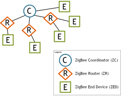
After looking at the XBee Series 1, we looked at the XBee Series 2 supports the ZigBee Protocol.[2][3] The ZigBee protocol is based on the IEEE 802.15.4 however allows for a (partially connected) mesh network topology. In the ZigBee protocol however, there is one "ZigBee Coordinator (ZC)" node that is responsible for the initial network creation and stores network information including the Trust Center and is the repository for the security keys for all of the nodes on the network. Then there are "ZigBee Router (ZR)" nodes which are responsible for routing messages from between nodes on the network. Finally, there are "ZigBee End Device (ZED)" nodes which only has enough functionality to send and receive messages to either the ZC or a ZR node (whichever node is its single parent). Once again, just like with the two previous designs, the loss of the coordinator node will severely limit the capabilities of the network. Also, because it stores the Trust Center, if authentication and security become an issue with the project, then the loss of the ZC node becomes catastrophic. The ZigBee Coordinator node is assigned at the firmware and so in the case of a loss of the ZC, a robot will need to be reprogrammed, dispatched and the entire network will need to be recreated. This also requires that an operator be in the area of the robots to be able to actually dispatch the new robot.
During our research we discovered that the previously discarded XBee Series 1 RF module was capable of a mesh network protocol as well. However, instead of the ZigBee protocol that the Series 2 uses, it uses a protocol called the DigiMesh Networking Protocol, which was created by Digi International, the company responsible for creating and manufacturing the XBee RF Module itself. In a whitepaper released by Digi about the differences between the DigiMesh Networking Protocol and the ZigBee Networking Protocol, Digi advertised that the advantages of DigiMesh were:
- Network setup is simpler
- More flexibility to expand the network
- Increased reliability in environments where routers may come and go due to interference or damage[4]
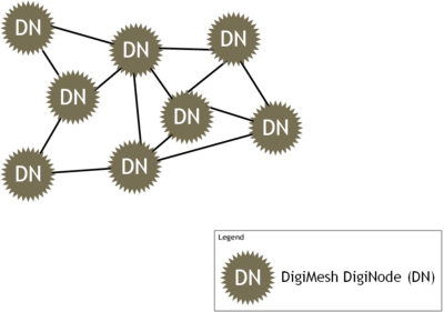
This last point is possible because the DigiMesh has only one node type, the "DigiNode (DN)." The DigiMesh network is a "homogenous network", where "all nodes can route data and are interchangeable" and there are no parent-child relationships. This means that the network is decentralized and the lack of a coordinator node required to setup the network means that the network can gain or lose robots with relatively few issues. Where in the ZigBee network, a ZigBee End Device (ZED) cannot mesh -- they have one specific parent (either a router or the coordinator) -- all DigiNodes are routers and can created a partially or fully connected network.[5]
| Network Protocol | Pros | Cons |
|---|---|---|
| 802.15.4 Protocol |
|
|
| ZigBee Protocol |
|
|
| DigiMesh Protocol |
|
|
Network Topology Examples
The following images are recreated from the images found in the ZigBee vs. DigiMesh whitepaper released by Digi International.[4]
|
|
Communication Method
The second problem that needs to be solved is that of sending instructions that the robots can process once the robots are on a physical network together. We need a protocol that is small enough that all of the different subsystems (such as the Arduino MCU or the Android phone in the current case) can parse the messages effectively.
One idea was to use the Simple Network Message Protocol (SNMP). SNMP is, as the name implies, relatively simple to use and is quite flexible/extensible because the protocol does not need to know the contents of the data payload that it carries. The problem with SNMP in the case of this project is that it may be unnecessarily large for our needs. The object identifiers (OIDs) in SNMP are unique worldwide -- each corporation that registers to use SNMP has a dedicated set of OIDs assigned to it to use, much like how IP Addresses are reserved in chunks for different uses. One of the other problems with SNMP using the hardware that we currently use in the COTS Bots project is that the available Arduino libraries that implement SNMP can take up a large portion of the available space on the Arduino Template:Cn.
Our next idea then was to create a protocol that was loosely based on SNMP but that did not have the features that we needed. For example, our OIDs could be unique just to the COTS Bots project -- this would reduce the size of each individual packet because fewer bits would need to be reserved for the address and the instruction type. The data payload would be similar to SNMP though because all it consists of is a field for length of the entire payload section and then the data itself. The payload inside the data section could then be formatted however the user wanted, including being nested data payloads.
Current Design
Our goal this semester has been primarily that of research -- our design is not final and is still subject to change throughout the next semester. However, for the current implementation, we decided to use the existing Arduino Romeo v2 MCU that is currently being used by our customers. This MCU has DC motor controllers built in -- installing them ourselves would be time-intensive and violates the COTS Bots ideal that says the robots should be easy to build.
The Romeo v2 also has a reserved section for attaching an XBee to it so there will be no shield required to use the XBee on the Romeo v2.
The Bluetooth also has a dedicated connection on the Romeo v2 board; however, in order for the Bluetooth and XBee to communicate at the same time, we need to use a Bluetooth shield. This is because both the dedicated Bluetooth and the dedicated XBee devices use the same pins to transmit and receive messages. By using a Bluetooth shield and an Arduino library called "SoftwareSerial", we can redefine which pins are used for transmitting and receiving on the Bluetooth shield.
We have decided to use a protocol that we have created that is loosely based on the Simple Network Message Protocol (SNMP). This lets us create small packets with any payload. This gives us future extensibility and flexibility for different tasks because the communication protocol does not need to have any information about what the data payload is made to do -- it just passes the information on to whichever node is requesting the information. The Android phone (in the current version of the project) is then responsible for translating the message and sending the necessary command to the necessary subsystem (likely on the Arduino MCU).
| Proposed Solution for COTS Bots Physical Layer Communication |
|---|
Fall 2014
Goals
- Research and select an upgraded hardware platform that can handle the extra communication channel.
- Enable phone to phone communication.
- Improve protocol for robot to robot communication.
- Positional Awareness - develop a system that would allow the robots to determine the position of other robots in the group.
- Begin design of the Android application.
Hardware Upgrade
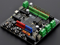
The Arduino MCU that was used on the current COTS robot was the Romeo V2 from DFRobot. The Romeo board is based on the Arduino Leonardo controller. This board has only a single hardware serial port. Two channels would be needed to handle simultaneous communication over the bluetooth and XBee devices. In the previous semester, they had success with using the SoftwareSerial library to create a virtual serial port. However after further testing, interrupt conflicts were observed between the virtual serial port and the motor controller.
Micro Controller and Shields
We chose to stay with the Arduino hardware platform to minimize the need to rewrite the existing code base. Several variants of MCU boards are easily available, and our major requirement for a new platform was that it needed more than a single hardware serial interface. A quick comparison between Arduino boards can be found [here]. Controller boards can be grouped into two sets, those with a single serial port, and those with four. Our choice was then between the Uno and Mega families. The COTS program here at the University of Idaho is an on going project that will continue. In order to allow for a high level of expansion available to future projects, access to add-on shields and software support, we selected the Mega platform.
Mega Features
- CPU - 16MHz
- Analog I/O pins - 16
- Digital I/O pin - 54
- PWM Pins - 15
- Serial - 4
- SRAM - 8kb
- Flash - 256kb
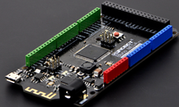
There are several different manufacturers creating Arduino compatible boards. In the end we chose the Bluno Mega 2560 from DFRobot. This board includes an embedded Bluetooth serial port. We will need an additional interface shield for our XBee modules.
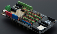
The interface shield we selected is the Mega Sensor shield from DFRobot. It includes three XBee form factor adapters and a micro SD slot. The board can be powered externally which will allow us to drive low amp motors directly.
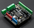
For higher amp motors, we also selected a 2A motor controller that will attach to the Mega Sensor shield.
Arduino Software Design
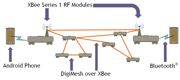
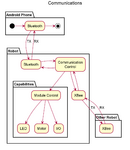
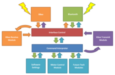
The general software design for the Arduino has two main components: Communication Control and Module Control. The Arduino is "spinal cord" for the Android "brain" and is simply designed to carry out the commands sent to it. The "brain" does not need to know how those commands are carried out, and the "spinal cord" does not need to know the reason behind the commands. Communications will flow through either the Bluetooth or the XBee, and robot commands can come through either channel. This design will allow for a single "brain" to control several robots.
Communication Control
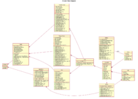
This module will control the Bluetooth and XBee modules and will parse all data and decide what to do with it. Data coming through any port will either be passed through to be sent on to it's destination, or sent to the Module Control to carry out the command meant for this robot. Each robot could have 1 or more XBee modules, with each one set to communicate with a separate network. A swarm of bots can be segmented into distinct groups that share a common network, but still able to talk with the bots in another network. Messages sent from the brain destined for another bot will get wrapped into the XBee protocol and sent through the Digimesh network. Received XBee messages are parsed to extract the payload data. The data will then be examined to determine which action is required, forward up to the brain through the Bluetooth, or forward to the Module Control to perform a robot action. The class diagram represents the current code base for the communication control.
Module Control
The capabilities of the robot, or all of the actions the robot is able to perform, are broken up into separate modules. Each module will control some specific set of like actions. The module control will determine which module a command is meant for and activate it. The system will be designed so that new modules can be added in the future. Within each module will reside the algorithms to interface with the Arduino hardware and carry out the desired commands. Each module will report back to communication control so that acknowledgements, errors or status messages can be returned.
Android Software Design
The brain of the COTS robots will be an Android smart phone. Development for the Android software will have two main components: the human machine interface (HMI) that will be used for manual control of the robot, and the application program interface (API) that will provide the front end code connections to use interface the Android and Arduino software and implement the communication protocols on the Android side.
HMI
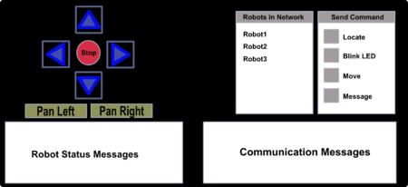
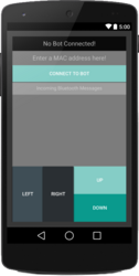
The HMI will allow for manual control of a robot. The HMI will mainly be used for demonstration and debugging purposes.
The screen will include:
- Movement Control: buttons to drive the robot and camera rotation
- Robot Status Window: to display activity messages from the linked robot.
- Robots in Network: display a list of other robots found in the network. The names can be clicked on to set them as the destination for a command to be sent.
- Send Command: list of available commands that can be sent to a robot.
- Communication Messages: display of text or status messages sent from a remote robot.
API
The API software will provide the link to the underlying communication and Arduino control methods. The API will provide the abstraction so that users will not need to know the specifics of how messages are sent or how the robot performs actions.
Software Test Suite
Testing is an important part of producing quality robust code. For this project, we have worked on two software testing libraries specially designed for this project.
Testing on the Arduino environment is hampered by the lack of convenient I/O capabilities. Often the LED or output through the USB port is used to debug problems with the code, however, this ability is limited and still requires the overhead of constantly uploading code and has no automated unit test ability. Therefore, in order to unit test the software before being uploaded to the Arduino, a Google Test Mock Arduino environment was created to provide basic unit and integration testing of the Arduino code on a PC. This allows basic C++ code testing along with a limited amount of Arduino specific testing, such as mocking the Serial ports.
Besides the development of a testing suite for the Arduino code, a Python3 based library for emulating the Android phone or a XBee network has also been started. This testing library will hopefully be able to increase the amount and speed of testing of some of the Arduino-Android and Arduino-XBee environments without the excessive overhead of manual testing, by emulating specific test cases without any hardware.
Positional Awareness
Successful completion of group tasks by a set of autonomous robots, requires that each member know the locations of the others members. With the addition of robot to robot communication, a method now exists for coordination.
Solution Requirements
- Easy to incorporate into current COTs design
- Fit on robot platform
- Able to be powered using current supply
- Follows COTS design requirements
- Commercial solution
- No soldering
- Accuracy
- Distance: resolution < 30cm
- Direction: +/- 5 Degrees
- Assumptions:
- Design of the solution assumes that the robots will have line of sight of each other
- GPS signal will not be available
- Other external sources for determining location are not present
Potential Solutions
- Signal Strength - The XBee wireless chips contain built in methods that record the signal strength for each message received. Strength of the signal could be used to determine distance of the sender. This method can make no determination of the sender's direction. Perhaps in a large network, a graph can be built using the calculated distance of each node to generate a working location map.
- Light and Sound - Additional hardware could be added to each robot that would make them capable of displaying a light source, LED, and a speaker and microphone for sending and receiving sound. Distance and direction would be determined by having a distant robot initiate a light and sound pulse at the same instant. The local robot would time the delay between the light and sound signals arriving.
- Precise Timing - Using the internetwork communication, timing signals can be relayed throughout the network to keep each robot's clock synchronized. Time stamps on messages could then be used to determine distance between the sender and receiver.
- Camera Perspective Size Change - The camera in the attached smart phone could be used to determine the distance to an object of a known size. Relative change in a size of an object based on pixel size can be used to calculate the distance of the object from the camera.
Proposed Solution Camera Perspective Size Change
- Benefits:
- Simplest solution.
- Able to determine both distance and direction.
- Will require the implementation of an additional wish list goal of creating a method for the attached phone to be able to move independently of the robot.
- Challenges:
- Incorporate additional motor and logic controls.
- Vision algorithms for finding the size of the distant object.
- Easy to see markers for determining edges of the distant object.
Size Markers
- Two LEDs separated by a known distance.
- LEDs placed on a vertical antenna attached to the robot.
- Vertical alignment allows for 360 degree view
- LEDs of different colors could provide visual contrast to assist with discovery algorithms.
Smart Phone Periscope Mount
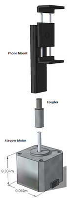
- Mount a smart phone to a stepper motor mounted vertically to the robot chassis.
- No cabling allows continuous rotation.
- Direction angle maintained by arduino logic. Homing or zeroing function will be needed to set zero angle after power up.
Position Calculation
- Direction
Using a rotatable mount for the smart phone, a search can be performed where the phone will pivot and scan its surroundings. While performing this scan, vision algorithms will be processing the live images, searching for the designated LED markers. Once they are in the field of view, the pixel measurement between the two LEDs will be used to determine distance.
- Distance
Distance will be estimated using the pinhole camera model[6]. Where the ratio of the pixel height of an object over the focal length is equal to the actual height of the object over the distance from the camera.
<math>\frac{\text{Pixel Height}}{\text{focal length}} = \frac{\text{Actual Height}}{\text{Distance}}</math>
To calculate the distance, we will first need to calibrate the system to determine the focal length. To accomplish this, we would need to set the remote robot a known distance away from the camera to be calibrated. Once the focal length is known, it can then be used to determine distance.
<math>\frac{x_1}{f}=\frac{X}{d_1}</math>
Where <math>x_1</math> is the pixel difference between the LEDs in the camera image. The actual height (X) is known. Distance to the object <math>d_1</math> can now be determined.
Accuracy Estimation
Assuming a camera resolution of about 1 megapixel or 1200 x 900 pixels.
- Distance Accuracy: +/- .33mm per pixel height change.
- Useful Range: .3m to 269m.
Spring 2015
Goals
- Complete Arduino Implementation
- Develop Android App for testing and debugging
- Complete Java API
Solution Design
Data Packet
- Simple packet design - data packets use simple array of byte codes to convey command group type, the action command, the command value and any options. The data packet will be wrapped into Bluetooth or XBee packets.
- Control Packet - data packet used for robot control commands, robot responses and data transfer.
- Communication Packet - data packet used for sending and receiving through the XBee network. Packet will contain a control packet as payload.
- No error correction byte - leverage the existing message integrity used in the Bluetooth and XBee protocols.
Arduino Software
- Low Memory usage - minimal use of dynamic memory at run time to reduce memory management.
- Least amount of processing - the intensive processing tasks will be performed by on the phone or attached brain. Arduino parses data packets, carries out command and generates the requested response.
- Minimal checks on commands - no decisions made by Arduino. Will carry out any valid command.
- Error Handling - maintain availability of robot. Bad packets are dropped and error responses are generated.
- Future Extensibility - designed so that future enhancement and capabilities can be easily added into the source code.
Android App
- Remote control for manual control of the COTS robot. Currently has functionality to drive the robot, discover all robots within the next and send a text message to any robot in the network.
- Debugging - main purpose of the app is for testing and debugging the communication and control between the phone software and the arduino software. Status windows display communication messages and any errors.
- Bluetooth API - software interface for communication with the robot. Enables XBee communication and motor control. New features can be quickly and easily added in the future.
Java API
Current software interface is incorporated into the Android app. Future work will be to take the current functionality and build a robust API that will be used to build future applications for artificial intelligence and machine learning activities.
Current Status
Arduino
- Motor controls and responses using control packets.
- XBee network node discovery.
- Processing of XBee send and receive data packets.
- Heartbeat system activity messages are functioning.
Android App
- Manual control of robot motors using command packets.
- XBee network node discovery and MAC address display.
- Send and receive strings through XBee network with display in status window.
- Heartbeat system monitor in separate thread with updates to status window.
- Control of Bluetooth resource.
Android API
- Incomplete - Modules baked into app source. Currently not a stand alone library.
Fall 2015
Goals
The Goal for fall 2015 is to get all the document, software, and hardware, and put them together and show working demo.
Team Biographies
Abdulmajeed Alotaibi
Computer Science
Hometown: Riyadh, Saudi Arabia
Bio:
Email: alot4458@vandals.uidaho.edu
Greg Donaldson
Computer Science
Hometown: ...
Bio: ...
Email: dona0579@vandals.uidaho.edu
Johnathan Flake
Computer Science
Hometown: Not relevant...
Bio: Currently studying computer science with a strong interest in game design and programming, Johnathan is also taking an evolutionary computation focused game design course with Professor Soule, one of the clients for this project.
Email: flak4202@vandals.uidaho.edu
Jason Kemp
Computer Science
Hometown: McCall, ID
Bio: Jason grew up in McCall, ID and graduated from the University of Idaho in 2010 with a Media degree. He returned in 2013 to complete a Computer Science degree. He currently has an internship with Schweitzer Engineering Laboratories in Pullman.
Email: jkemp@vandals.uidaho.edu
Gabriel Pearhill
Computer Science
Hometown: Pocatello, ID
Bio: Gabe is currently working with Idaho RISE and NASA Ames Research Center to create cheaper telemetry systems for high altitude balloons and small satellites. He is currently studying evolutionary computation with Professor Heckendorn, faculty adviser for this project.
Email: pear9115@vandals.uidaho.edu
Matthew Trana
Computer Science
Hometown: Moscow, ID
Bio: Currently working at Schweitzer Engineering Laboratories as an Equipment Programmer. He is currently studying Evolutionary Computation and will be graduating this semester. His interests include embedded software and data analysis.
Email: tran2733@vandals.uidaho.edu
