Electric Forklift Battery Cooling
| Sponsors | |
| Team Name | Cool Charge |
| Duration | 2018 - 2019 |
| Faculty Adviser |
|
| Mentor |
|
| Client |
|
| Team Members |
|
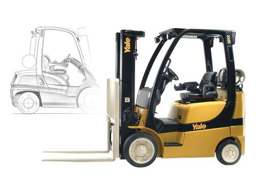
Hyster-Yale produces a variety of lifting trucks. In an effort to be more globally responsible and eco-friendly, they are working on expanding their line of electric forklifts. The lithium-ion batteries used in these systems create excess heat when charging or discharging quickly. If this heat is not removed properly, the batteries have a safety feature which limits the current and in turn greatly reduces performance and efficiency. With the present cooling system, the forklift should be able to operate normally in ambient temperature up to approximately 30°C. However, many locations where Hyster forklift are being used have ambient temperatures which reach 40°C. The Cool Charge team has been responsible for the design of a more efficient, higher capacity cooling system to handle these higher ambient temperatures. The engineering solution will allow Hyster-Yale’s electric vehicle technology to be used in more locations and markets and aid in reducing the use of fossil fuels.
Problem Definition[edit | edit source]
Background[edit | edit source]
Hyster-Yale produces a variety of lifting trucks. In an effort to be more globally responsible and eco-friendly, they are working on producing a line of electric forklifts. This creates an excess of heat that needs to be removed to allow the batteries and motors to operate at optimal efficiency. With the current setup, the system is effectively operable up to an ambient temperature of approximately 30°C. However, in many locations the ambient temperature can reach 40°C.
Deliverables[edit | edit source]
- Proof on Concept Prototype
- Prototype to cost less than $1000 per unit to produce.
- Solid Model
- The prototype model is to be modeled in SolidWorks.
- The model is to include a heat transfer and airflow analysis.
- Heat transfer Calculations
- Calculations done to represent total energy removed from the battery module under given conditions.
Specifications[edit | edit source]
Functionality[edit | edit source]
- The heavy-duty cooling system should be able to remove 100 Watts of heat from each battery module.
- The heavy-duty cooling system should cool the battery during charge/discharge at a rate of 1C.
- The heavy-duty cooling system will replace the standard cooling system for equipment operated in ambient temperatures of up to 40.
- The heavy-duty cooling system should be able to remove 100 Watts of heat from each battery module.
- The cooling system is expected to maintain internal battery cell temperatures at or below 55 °C by removing heat from the batteries modules.
Mechanical[edit | edit source]
Spatial[edit | edit source]
The cooling system needs to fit within the compartment behind the battery assembly and in front of the forklift counter weight.
- The heavy-duty cooling system dimensions will be:
- Height < 502 mm
- Width < 652 mm
- Depth < 272mm
Mounting[edit | edit source]
- The heavy-duty cooling system needs to mount in the same position as the current cooling system.
- Cooling system components will be mounted using the same mounting hardware as the current cooling system.
- Additional heat transfer equipment will possibly mount in the 10mm slots between battery cells.
- The mounting system shall be able to withstand vibrations from daily equipment operation.
Electrical[edit | edit source]
Cooling System Operational Specifications[edit | edit source]
- During operation, the cooling system supply voltage shall remain at 12 Volts DC.
- During operation, the system shall draw no more than 15 amps.
- During operation, the system shall use no more than 180 watts.
Battery Unit Specifications[edit | edit source]
- The individual battery voltage is 51 Volts.
- The individual batteries are rated at 174 Amp-hours.
- The individual battery units have a high-speed discharge rating of 350 Amps.
Environmental[edit | edit source]
- The cooling system is expected to operate in environments with ambient temperatures between -10°C and 40°C.
- The heavy-duty cooling system shall resist water ingress, rust and corrosion on components and in connectors.
- The system shall withstand normal equipment cleaning procedures including pressure washing.
Project Learning[edit | edit source]
Battery Tests[edit | edit source]
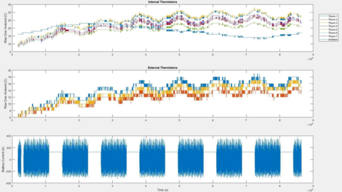
This test was run by Hyster-Yale workers in an environment with an ambient temperature of 15-20 Celsius. This was run with no external cooling, only natural convection. As you can see the temperature seems to peak during charging, the flat area on the Current vs. Time plot. This assisted us in deciding that most of the cooling needed to take place during the charge cycle. However, that is not to say that the discharge cycle does not need cooling. This, in conjunction with the following image helped us narrow down the actual wattage of the batteries, as well as a surface and internal temperature to work with for calculations.
Fluid Flow[edit | edit source]
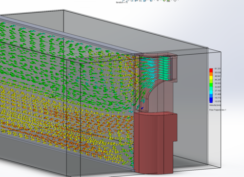
The team decided to use SolidWorks for all of our thermal and computational fluid dynamics (CFD). The first model we worked on was CFD model to show how the airflow through the slot acted. Figure 1 shows the CFD created. Air enters the ducts @ 110 ft^3/min. The top and back of the slot have atmospheric pressure built into the model. You can see where the air enters at about 40 m/s, and as it goes through the slot it speeds up to around 55 m/s. Once the air levels off further down the slot, it reduces to the mid 30’s m/s.
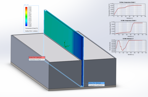
The last CFD model we created was to see how much the air is heating up as it travels down the side of the battery. To do this, we created a CFD model while plugging in how hot the air incoming was, as well as how hot the sides of the battery were (50 C). The air enters @ 220 ft^3/min and a@ 40 C, which is ambient air temperature. Figure 2 shows how the air heats up as it travels down the battery module, making it about a third of the length before becoming warm again.
Thermal Analysis[edit | edit source]
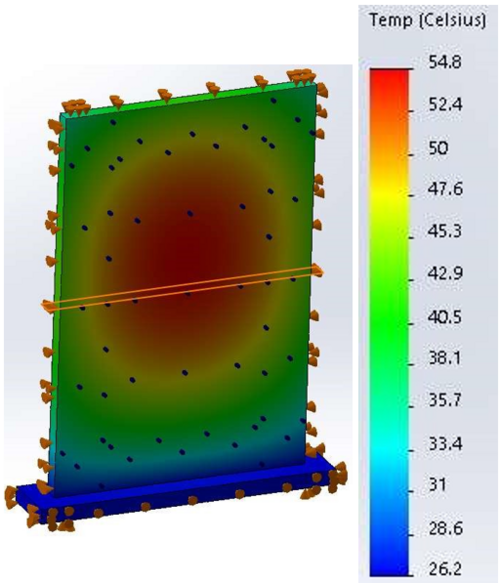
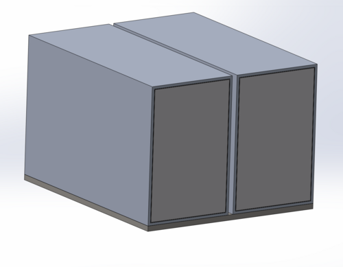
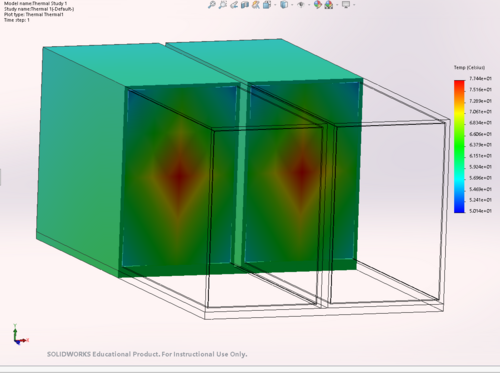
The thermal analysis was a bit trickier in SolidWorks. To understand what was going on, the team worked with hand calculations so in the end we could double check all of our work. The first figure shows the initial internals of the battery, and the second shows the thermal model generated. This model was generated to see exactly how the battery heats up. The center core of the batteries have a very low thermal conductivity (1.5 W/ (m-K), therefore the center of the batteries are going to be very hot. There is then a thermal paste around the inside of the battery that has a similar thermal conductivity to the inside. This thermal paste bonds to the aluminum shell, and is then set on a steel plate. In SolidWorks, you have to set a thermal resistance between any faces that come in contact with each other. To do this, I did hand calculations of all of the touching faces to find the thermal resistance using the equation R_Thermal = L/(kA) where L is the characteristic length (m), k is the thermal conductivity (W/m-K), and A is the cross sectional area of the touching faces (m^2). After doing that I plugged those into SolidWorks. The next step is the heat generation. We were interested in a uniform heat generation of 200 W per battery module. Finally, I added in natural convection from standing air, using an h = 20 W/(m^2-K). The max internal temperature of the batteries ended up being 73.4 C, which was extremely close to a bench top test our client did.
Heat Pipes[edit | edit source]
Heat pipes are a passive way of moving heat from one location to another. They are an evaporator-condenser system contained inside of a pipe, generally copper. Heat pipes would be used to move the heat from the walls of the batteries to a location with more space so that the heat could be rejected easier. They can be very quick and efficient, however, they work better at shorter lengths. Seeing as our battery modules are rather long they are not a very viable option. Here is some of the research on heat pipes:
Peltier Modules[edit | edit source]
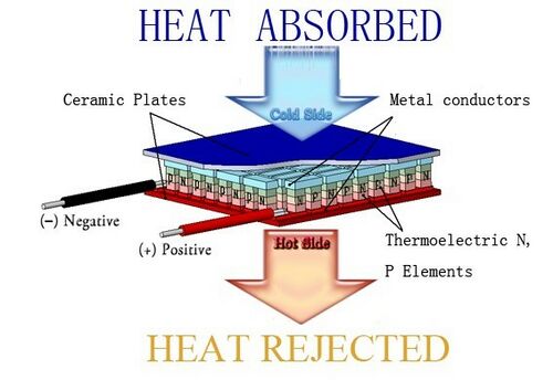
Peltier modules are a thermoelectric device that operates on 12 volts. They have one hot side and one cold side. For the purpose of cooling down the batteries, we could use the modules in two different ways. The first would be to attach the cold side directly to the wall of the batteries, but this would still leave the hot side just radiating into the gap. The second way of using them would be to set them up at the intake so that the cold side would cool down the air, and the hot side could be vented into the atmosphere more easily. Here is some more information on Peltier modules:
Refrigeration Cycles[edit | edit source]
Refrigeration cycles have four main parts: an evaporator, compressor, condenser, and expansion valve. The function of the evaporator is to absorb heat and boil the refrigerant, usually R-134a. The phase change is what allows the evaporator to absorb heat (any substance takes in energy when changing from a liquid to a gas). From the evaporator the gas is drawn in to the compressor and then compressed to a point where the gas is at higher pressure and temperature. Next the refrigerant is pushed into the condenser where the gas releases heat and changes back into a liquid. The expansion valve allows the refrigerant to expand causing a pressure drop. Then the refrigerant is returned to the evaporator and the cycle repeats. This system can be modeled as an ideal compression cycle. After sizing and selecting components, the component efficiency can be added to the model and accurate predictions about the system can be made.
Final Design[edit | edit source]
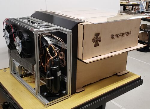
Our final design has a disassembled window air-conditioning unit housed within an 80/20 extruded aluminum frame. This modular frame design will allow for adjustments of minor location changes, and will make any more additions or changes simpler. It also contains the entire system in one relatively easy-to-handle system that keeps the dimensions to the specifications given to fit in the forklift. Below you can see a few images with more explanation of the system.
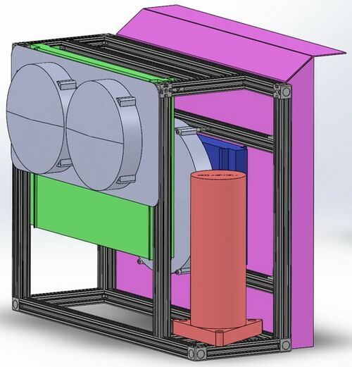
Here you can see the entire assembly as viewed from its right side.The compressor from the AC system is the red cylindrical part. There will be hosing connecting that to both the evaporator (blue) and the condenser (green). The large pink piece on the back is a sheet metal shroud that will allow the cold air being pushed and pulled through the evaporator by the two large fans to travel through the battery gaps with minimal loss. One of those fans is not shown in this image, as it is on the other side of the shroud.
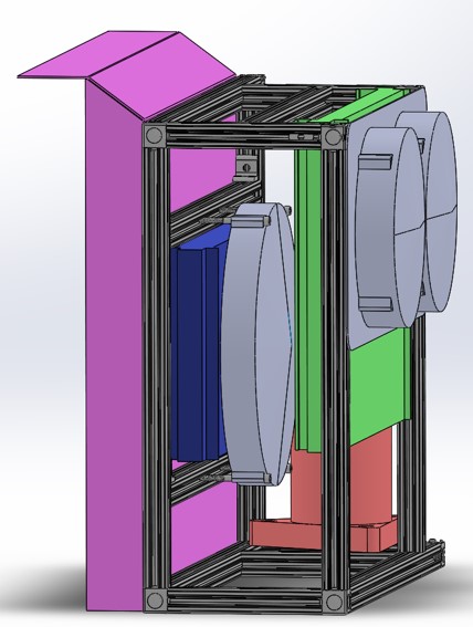
The larger fan on the evaporator can be seen more easily in this image. It can also be seen, perhaps more clearly in this image, that the condenser had to be shifted as far to the left as possible to avoid contact with the compressor on the other side. The two fans mounted on the condenser will pull air through the condenser and 'exhaust' it through a hole in the counterweight.
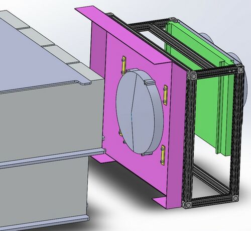
In this image you can see the fan on the inside of the shroud that will be pulling the air through the evaporator in combination with the other pushing fan. The idea behind the two fans is that each fan will help the other out, to eliminate or minimize the effects of friction and back-pressure while maintaining high flow rates.
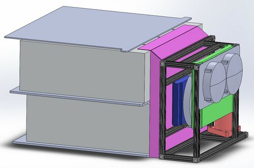
Here is the entire assembly shown as it would be mounted against the battery pack itself.
After assembly and completion, this is what the entire unit look like up against the finished mock-batteries that were created.
Validation[edit | edit source]
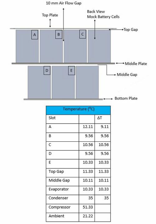
After construction of our final product, we ran several tests to find the difference in temperature that our refrigeration cycle was producing. The results of this can be seen below.
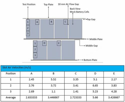
The image above the table shows the locations that each section on the table corresponds to. In a similair style, the images below represent the airflow speeds that we recorded.
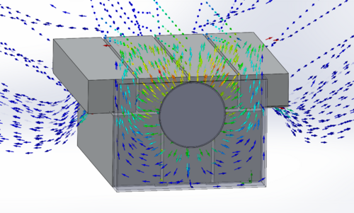
We then took our data form our practical tests, and compared them to an updated CFD analysis, which can be seen below. We got slightly less cooling than we expected before, and slightly less airflow compared to our first CFD. However, in our first CFD we did not account for airflow over the top and outside of the batteries, so we expect that the battery cooling from this will make up for the slightly slower speed.
File:Hyster Design Validation Plan.pdf
Team Members[edit | edit source]
| Chase Dinning
Major: Mechanical Engineering
| |
| Trevin Kretz
Major: Mechanical Engineering
| |
| Beau Nuxoll
Major: Mechanical Engineering
| |
| Chris Standley
Major: Mechanical Engineering
|
Additional Documentation[edit | edit source]
Project Schedule
Meeting Minutes
[[File:]]
Presentations
File:Cool Charge Concept Design Review.pdf
File:Cool Charge Design Review.pdf
[[File:]]
[[File:]]

