Geometric Dimensioning and Tolerancing
Geometric DImensioning and Tolerancing (GD&T) is a system of rules and symbols used for describing the geometry of parts. Common GD&T practices provide accurate communication of design intent between manufacturers, engineers, and machinists.
Theory[edit | edit source]
GD&T is a compact language for describing a part that replaces notes with symbols. It is used worldwide under the ISO 1101 and ASME Y14.5M standards. This system is defined by the tenants of clarity, improved inspection methods and realistic tolerances that give manufacturers better control of fit, function and design. GD&T practices allow for the control of a parts dimensions and geometric qualities such as flatness, roundness, symmetry and more. These practices have grown in use with the globalization of the manufacturing market. If a company outsources the manufacturing of a part, there must be standards to assure that there designs and the manufacturers match. GD&T facilitates precise control over parts regardless of construction location. ie: a part made in Germany will fit with the housing made in the U.S.
Dimensioning[edit | edit source]
To build an object as precise as possible, complete information about shape and size of the object must be available. Orthographic drawings, developed following standard drawing practices, are used to express the exact shape of an object. Most drawings included shaded models and orthographic drawings for the person building the part can see understand, and visualize the part clearly. Dimensioning a drawing can be described as the process of adding size information to the drawing [1].
The science of geometrics is applied to specify and tolerance the shapes and locations of features on objects. Once an orthographic drawing has enough information to fully define the shape the size specifications can be added in the form of dimensions. Note that by dimensioning a drawing, the tolerance for each dimension can be identified. Graphics, dimensions, and words are the three elements for a fully defined part that make the intent of the designer clear to the person building the part as well as the inspector inspecting the part. Moreover, it's important to take into consideration that the necessary information to make the object is present, without excessive dimensions such as duplicating a dimension or dimensioning the same feature in multiple ways [1].
The dimensioning of parts is based on:
- "Basic size and locations of the features"
- "Details of a part's construction and for manufacturing" [1].
Vocabulary[edit | edit source]
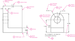
Some important terminologies to specify size and location of features illustrated on the drawings by numbers are:
- Dimension: "is the numerical value that defines the size or geometric characteristic of a feature"
- Basic Dimension: "is the numerical value defining the theoretically exact size of a feature"
- Reference Dimension: "is the numerical value enclosed in parentheses provided for information only and is not used in the fabrication of the part"
- Dimension Line: "is the thin solid line which shows the extent and direction of a dimension"
- Arrows: "are placed at the ends of dimension lines to show the limits of the dimension"
- Extension Line: "is the thin solid line perpendicular to a dimension line indicating which feature is associated with the dimension"
- Leader Line: "is the thin solid line used to indicate the feature with which a dimension, note, or symbol is associated"
- Tolerance: " is the amount a particular dimension is allowed to vary"
- Plus and Minus Dimensioning: "is the allowable positive and negative variance from the dimension specified"
- Limits of Size: "is the largest acceptable size and the minimum acceptable size of a feature"
- The largest acceptable size is expressed as the Maximum Material Condition (MMC)
- The smallest acceptable size is expressed as the Least Material Condition (LMC)
- Diameter Symbol: "is the symbol which is placed preceding a numerical value indicating that the associated dimension shows the diameter of a circle. The symbol used is the Greek letter phi, ∅"
- Radius Symbol: "is the symbol which is placed preceding a numerical value indicating that the associated dimension shows the radius of a circle. The radius symbol used is the capital letter R"
- Datum: "is the theoretically exact point used as a reference for tabular dimensioning" [1]
Practices[edit | edit source]
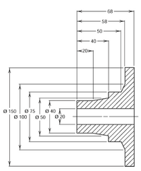
- Placement: The placeent of dimensions are dependent on the available space between extension lines. If there is enough space, dimensions and arrows are to be within the extension lines as shown in Figure 2.
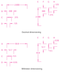
- Grouping: Dimensions are to be grouped for uniform appearance illustrated in Figure 3. Dimensions should be co-linear when possible.
- Staggering: is to stagger values into parallel dimensions, shown in Figure 4.
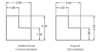
- Reading Direction: The orientation of all dimensions and note text is to be readable from the bottom of the drawing relatively to the drawing format.
To place dimensions and text to be read from the bottom of the drawing is known as unidirectional dimensioning. To have text placed parallel to dimensions and text with vertical dimensions read from the right of the drawing is called aligned dimensioning.
Guidelines[edit | edit source]
The guideline is that of clarity and if two guidelines seem to conflict, the one that most clearly represents the size information is to be used [1].
- Every dimension should bring a connected tolerance, and the tolerance must be clearly demonstrated on the drawing.
- Over-dimensioning a part is to be avoided. It is impermissible to double dimensions a feature.
- Dimensions are to be placed in a position that most clearly demonstrates the feature being dimensioned.
- The spacing between the object and dimensions and between dimensions is to be maintained at minimum.
- There has to be a visible gap between the feature being referred to and the end of extension lines.
- Unless no other way of manufacturing is satisfactory, manufacturing methods ought not be specified as part of the dimension.
- When practicable, dimensions being placed within the boundaries of a view are to be avoided.
- Dimensions of materials normally manufactured to code numbers or gauges are to be specified by numerical values.
- Angles indicated on drawings are assumed to be 90 degrees unless otherwise specified.
- When possible, using hidden lines to dimension should be avoided.
- The depth of countersunk, counterbored, or blind holes can be added in a note along with the diameter. All information about a hole should be in one callout.
- Appropriate symbols should be used preceding the numerical values to specify diameters, radii, squares, countersinks, spotfaces, counterbores, and depth.
- Leader lines in radial lines should be used for diameters and radii.
Tolerancing[edit | edit source]
Tolerance: "is the total amount a dimensions may vary and is the difference between upper (maximum) and lower (minimum) limits. Tolerances are used to control the amount of variation inherent in all manufactured parts. In particular, tolerances are assigned to mating parts in assembly" [1].
With the use of tolerancing, interchangeable parts are possible, which is a great advantage of tolerances. Moreover, they're used making drawings to manage manufacturing processes more precisely as well as to control variation between parts [1]. However, to get more accurate and precise parts, more time is needed to be spent and that will increase the cost. Therefore, whenever possible, only specify a critical tolerance if there is a need for a part to have high precision, such as when there is a type of fit specified.
Tolerance Stack Up[edit | edit source]
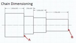
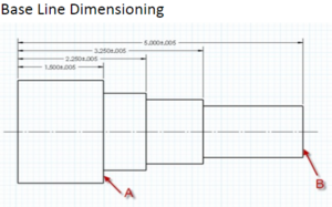
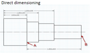
The reference frame of a dimension has an indirect effect on its tolerances. If a features dimension is referenced from another feature, instead of the datum, then that dimension can vary as much as its own tolerance and the tolerance of the feature it is referenced from. Due to this, different dimensioning techniques are used based upon what dimensions are critical.
- Chain Dimensioning features the greatest stack up of tolerances along a part and should be avoided.
- Baseline dimensioning has a tolerance stack up between two features equal to the sum of the two features tolerances. It is a safe way to keep stack up low across an entire part.
- Direct dimensioning calls specific distances between important parts to prevent stack up for highest accuracy. This method should be used to draw attention to key features on a part where distance must be strictly controlled.
Feature Control Frame[edit | edit source]
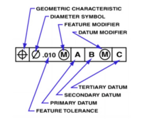
A features tolerance information can be described in a box, which reads from left to right, called a feature control frame.
- The first space describes the characteristic of the feature (position, flatness, etc).
- The second space defines the tolerance of the feature, tolerance zone, and any material condition modifiers.
- The following spaces contain the primary datum and any tertiary datums and material condition modifiers that apply.
Tolerance Boxes[edit | edit source]
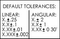
Default tolerances are located in boxes like the one on the right. These provide information about standard tolerances based upon number of decimal places on a given dimension on an engineering drawing. When creating drawings it is important to understand the default tolerances effect on machining difficulty when defining part dimensions. Low importance dimensions need fewer decimal places.
Fits[edit | edit source]
Although there is a granulated spectrum of engineering fits, they can be generalized into a few categories.
- Slip Fits
Slip fits allow for easy removal of a part. best practice for these fits are to under size the size of a part by a a few thousandths of an inch.
- Interference Fits
They occur "when two toleranced mating parts will always interfere when assembled" [1]. These fits use the forces of friction and compression to fix a part in place. For this type of fit the part is sized 1 or 2 thousandths larger than its slot. Because the part is deformed when it enters the slot
- Clearance Fits
These occur "when two toleranced mating parts will always leave a space or clearance when assembled" [1].
- Transition Fits
These occur "when two toleranced mating parts will sometimes be an interference fit and sometimes be a clearance fit when assembled" [1].
Practices[edit | edit source]
- Floating Fastener Tolerancing: is performed to confirm that loose screws, bolts, or other fasteners have the standard clearance in their holes [1].
- Fixed Fastener Tolerancing: is performed similarly as floating fasteners with the exception that fasteners are already fixed/located on once of the mating parts and the tolerance is divided between the parts [1].
- Hole Diameter Tolerancing: is performed to determine the MMC of the hole [1].
Symbols[edit | edit source]
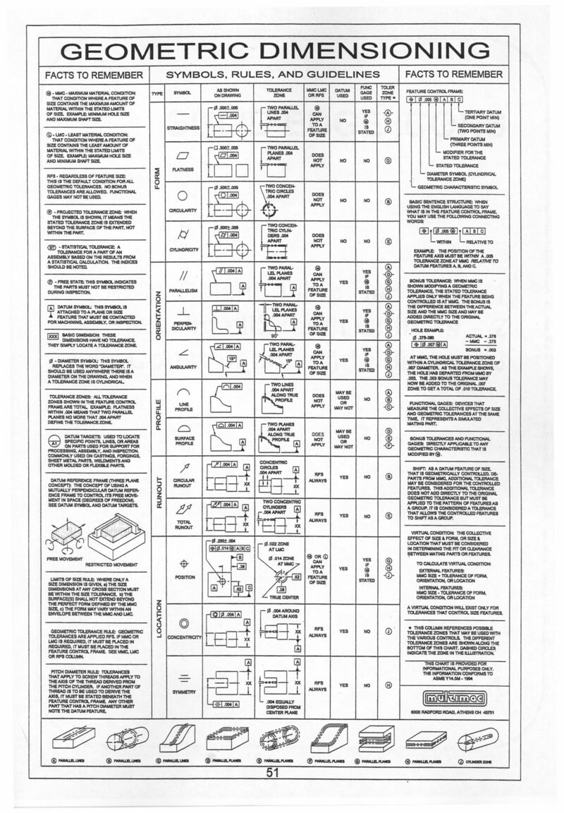
The following is a table of important symbols, rules, and guidelines [2].
References[edit | edit source]
[1] http://engineering.pages.tcnj.edu/files/2012/02/dimensioning_and_tolerancing.pdf
[2] http://www.ohio.edu/people/cyderst/gdnt_refsheet.pdf
