INL - Grinder Water Circulation and Filtering System
|
| |
| Sponsor | Idaho National Laboratory |
| Advisor | Dr. Matthew Swenson |
| Duration | Fall 2017 - Spring 2018 |
| Mentor | Alex Olson |
| Team Name | Keep It Clean |
| Students |
|
Idaho National Laboratory (INL) has reached out to the University of Idaho to completely re-design a water filtration system that is to be used in a hot-cell environment. Our team is working closely with the staff here at The University of Idaho along with INL to ensure that our system meets all of the specific requirements. On this page we talk about the system we designed and built, decisions we made, and we will provide as much information on our project as possible. Overall, our project was a success and we are excited to share our work with you.
Project Definition[edit | edit source]
Problem Statement[edit | edit source]
For this project, we were tasked by Idaho National Laboratories (INL) to redesign a grinder/polisher water filtration system. The main function of this system is to rinse off a grinder and polisher within a hot-cell, filter the particulate and water solution, and recirculate the clean water back on the the grinder and polisher. The current system in use by INL needs to be redesigned because it needs cleaning often, the filter is expensive and inefficient, and the pump gets exposed to particulates from the grinder and polisher. As these are our three biggest challenges, we set out to design a system that focuses on particulate centralization and filter efficiency. Solving these issues will result in a system that can work for long durations and can be easily replaceable when needed.
Specifications[edit | edit source]
Project Design[edit | edit source]
Design Alternatives[edit | edit source]
Filter Alternatives[edit | edit source]
Tank Alternatives[edit | edit source]
Pump Alternatives[edit | edit source]
Design Selection[edit | edit source]
Filter Selection[edit | edit source]
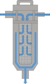
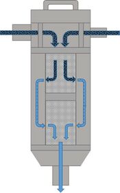
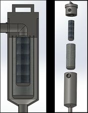
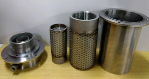
Overall, we are very pleased with the design of our filter and we think that it did a good job of meeting all our specifications. One thing to note is that we did go back to having the bypass come back into the top of the filter. Although in this design it does not actually go through the filter cartridges it just runs along the side of them so that it can help direct the flow. The top of the filter is made from a solid stainless-steel block which overall made it heavy. The filter housing is made from a 5-inch diameter schedule 40 pipe, and we were pleased with how it worked in our system. To mount the top of the filter to our filter housing and we had to come up with a unique idea. We created a flange system that was welded to both the top and to the filter housing. We made two identical flanges and welded them into place so that the top of the filter would be able to mount to the filter housing in four different locations. Overall, this is a well-done design and it did a good job of achieving what we hoped when we were initially designing.
Tank Selection[edit | edit source]
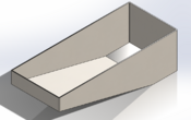
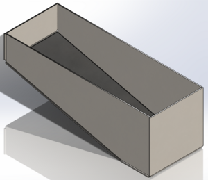
There were two main criteria that we wanted to meet with the tank. First, we wanted the tank to be easy to clean. Second, we wanted something that would be easy to manufacture. We believed that our first initial concept fit those criteria the best. The design was then altered when we learned that the pump had a longer shaft than what we were expecting. Later we had determined that we wanted to reduce the amount of welding on the tank to minimize places for leaks to occur. This led to the creation of a flat pattern for out first initial concept. However, later we discovered that our design would require tooling to be made in order for it to be bent. Which is what led to the final design having the side sheared off, inset an eighth of an inch and then welded back on.
Pump Selection[edit | edit source]
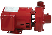
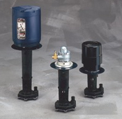
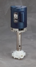
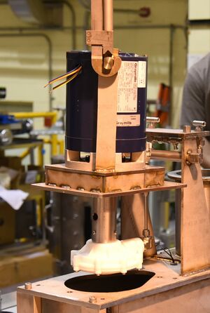
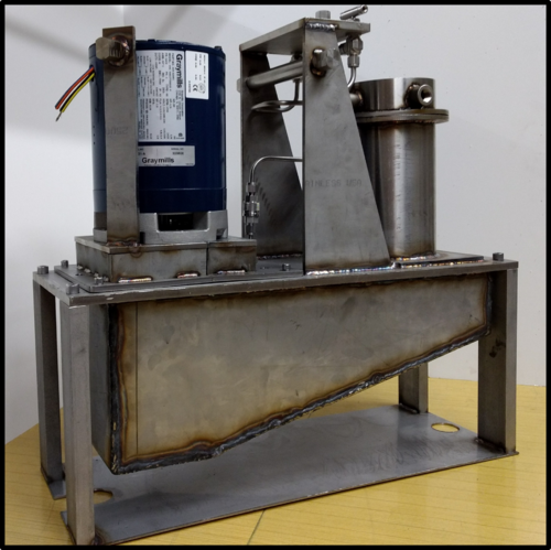
Looking deeper at the LV series there are many options to choose from. The pump that correlates best for the required head and system architecture is the LVM21A pump. This pump runs at 1/8 hp, has a shaft length of 8 ⅝ inch, and requires 115 volts. In addition, the discharge port of this pump is ¾ inch National Pipe Thread. Provided that our tubing is only a quarter inch, a ninety degree elbow with a reducer threads directly into the pump discharge port to be compatible with our tubing. One of the bigger challenges of this pump is the ability to mount it. The final pump mount design is a two part mount that bolts to the bottom of the motor body with ¼-20 bolts. The two part design is essential as the diameter of the impeller is the same as the motor body making it impossible for a mount to simply slip on over the impeller. As one can see from the above picture, the two part mount comes together around the shaft and is then bolted. Due to the length of the shaft, the mount is designed so that the bottom of the motor body is elevated 1.75 inches off of the deck plate. This allows the inlet of the pump to have clearance off the bottom of the tank. This clearance is essential to avoid cavitation.
Integration Selection[edit | edit source]
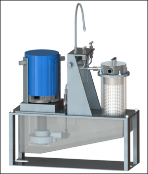
This is the final integration design with all the placing of the components. This design is elegant, easy to manufacture, and completes all the design tasks we need to reach the client’s needs. This design places the filter before the pump, much like the other designs, but does not have the bypass going into the filter. The filer will run completely gravity fed into a slanted tank as opposed to the flat tank of the other designs. The pump is places on the other end of the table at the end of the tank and pumps out into minimal tubing which allows for lower head loss. There is a T-joint at the maximum height constraint that allows for two values to be places on the ends of the T-joint. These values are for controlling the flow onto the grinder and creating a bypass tube for excess flow from the pump. This design is what we ended up building for our project.
Implementation[edit | edit source]
Although the design met all client specifications, there were some improvements that need to be made to our design before it could be used at INL. These changes were suggested to us by INL and are as follows: incorporation of flexible tubing, moving the bypass to enter the filter housing, changing of the type of Swagelok quick disconnects, varying the heights of the guide pins, and t-bar handles on screws. The flexible tubing was suggested to us during our last visit with INL. In the final concept, the tubing cannot be removed easily with the mechanical manipulators, which makes it almost impossible to remove sections of our system in the hot cell. Flexible mesh tubing is available on the market and can be purchased for around the same price of the current tubing, which is about $200. Using this tubing throughout the whole system is recommended, as the manipulators can move the flexible tubing out of the way if it becomes a hindrance to the working environment.
Team Information[edit | edit source]
| Biography | Discipline | ||
|---|---|---|---|
| Drew Fagan |
Drew Fagan is a senior in mechanical engineering at the University of Idaho. His interests include vibration and acoustic analysis. He hopes to continue his knowledge in these areas with the Naval Surface Warfare center to try to help the submarine fleet stay undetected in dangerous waters. |
Mechanical Engineering. | |
| Jerry Kahn |
Jerry Kahn is a senior in mechanical engineering at the University of Idaho. His interests are in design and nuclear power. Currently, his goals are to work in industry for a few years then return to school for nuclear engineering. |
Mechanical Engineering | |
| Thomas Moore |
Thomas Moore is a senior in Mechanical Engineering at the University of Idaho. He is interested in machining and design, and hopes to work in a fast pace atmosphere after school. His current goal is to work in the field for a few years before returning to school to work towards being a professor. |
Mechanical Engineering | |
| Troy Sanders |
Troy Sanders is a senior in Mechanical Engineering at the University of Idaho. His interests include design work and piping and HVAC systems. He is passionate about roller coasters and hopes to one day design roller coasters or work on hydraulic launch systems for roller coasters. |
Mechanical Engineering |
