LED Display 2014-2015
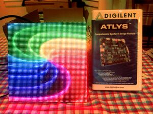
LED Display is an attempt to create a clear, bright, and cost-effective medium for displaying video to be viewed during any time of day and from a distance. Some of the goals of the project for the 2014-2015 academic year is to improve the quality of the video, to add HDMI input, and to extend the size and resolution of the display.
| LED Display | |
| Sponsor: | Dr. Robert Rinker |
| Duration: | Fall 2014 - Spring 2015 |
| Mentor/Faculty Advisor: | Professor Bruce Bolden |
| Team Members: | |
Problem Statement
The past senior design project LED Video Player allowed us to drive full-motion video to LED panels using an FPGA.
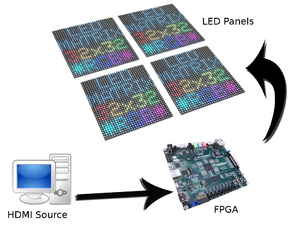
The system we developed for this project lets us send an HDMI video signal directly to an FPGA. The FPGA can pass a scaled down copy of the video to the LED panels. This allows for "plug-and-play" usage with any progressive and 640x480 HDMI source, without the need for a computer, and with little configuration required.
Background
LED panels are used around the world for businesses large and small. However the choices are a little lacking when it comes to inexpensive solutions that are easy to use, open source, and that work with commodity hardware such as the Adafruit LED panels. With our project files anyone can use an HDMI capable FPGA to drive Adafruit LED Panels.
The previous LED Video Player project was a good start, but it had some downsides and required custom software. In our LED Display project we hope to make sending video to a LED panel as easy as plugging in an HDMI cable.
Previous Work
Main page: LED Video Player.
Specifications
| General Requirement | Specific Requirement | Target Values | Achieved Values |
|---|---|---|---|
| Full Color | The LED panels colors should look good | The LED panels should output around at least 12-15 effective bits per pixel | The LED panels can display full 24-bit color |
| Plug-n-Play | The LED Display should work with a variety of HDMI source devices. | The LED Display should support EDID identification with an input resolution of at least 640x480. | EDID identification is supported, and the FPGA can receive a progrssive 640x480 HDMI signal. |
| Framerate | The displayed video should look smooth. | The display should run at at least around 24 FPS, or at least look OK. | We didn't measure the final framerate, but it looks smooth. |
| Stability | Everything should work. | Video glitches should be rare. The LED panels shouldn't melt. The FPGA shouldn't explode. The HDMI video sink shouldn't give up the ghost. | Picture is perfect with scaling disabled. Picture has some artifacts with basic scaling enabled. |
| Tile-Ability | LED panels should be able to be tiled and reconfigured. | LED Display should support one tile, or three tiles across and two tiles down. LED display must be able to be manually reconfigured (doesn't have to be user friendly) for either of these arrangements. Ideally other configurations such as 6 tiles across should be supported. | We only wired up a 2x2 square, but the Verilog HDL is very flexible. |
Design
Existing Work
The HDMI2USB project on github has a lot of existing opensource HDMI HDL. In particular the HDL for recieving HDMI video and for acting as an EDID slave has proven to be very useful.
Project Learning
HDMI Basics
HDMI is based on DVI, and as we’re only concerned with unencrypted uncompressed video, a lot of our work will actually be DVI work in disguise.
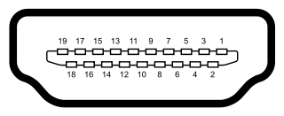
A typical HDMI connector looks like this:
Features:
- Hot plug detect detects when the cable is plugged in or not.
- DDC is an I2C based protocol and stands for Display Data Channel. Having this working is a requirement for being an HDMI sink, as it’s what tells the source the # display capabilities and whatnot.
- CEC stands for Consumer Electronics Control. It’s a bus that can chain multiple HDMI devices together for things like allowing a remote to operate all devices at the same time.
- TMDS is a differential signalled pair of wires that send over bytes of data using an 8b/10b encoding. There are three different TMDS pairs.
TMDS
TMDS stands for transition minimized differential signalling. The “transition minimized” refers to trying to minimize transition between zero and one, as well as trying to keep the 0’s and 1’s balanced. This is important for electrical reasons.
The “differential signalling” refers to sending a signal over a pair of wires. One wire carries the complement signal of the other wire. This can help protect against interference as the interference will probably effect both wires similarly.
There are three TMDS channels (or six for the Type B cable), one for each color out of Red, Green Blue. Each one of these needs to be 8/10 encoded seperately. The pixel clock is also sent over a DS pair, but isn’t 8/10 encoded.
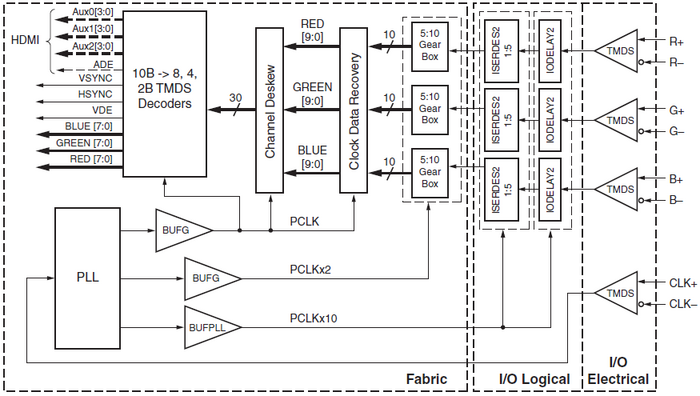
Here is a block diagram of the Xilinx TMDS receiver we used:
8/10b Encoding
HDMI uses an 8/10 encoding where an 8 bit word is transformed into a 10 bit word with properties good for the “transition minimized” goal.
As each 8-bit color needs 10 bits to transmit, this means the bits have to be sent 10x the speed of the pixel clock.
The algorithm is a bit involved, but comes down to some simple combinatorial logic. Basically it chooses either XOR or XNOR to encode the 2nd through 8th bits based on what will minimize transitions. Then it sometimes inverts the signal to keep 1’s and 0’s balanced.
DDC
DDC is an I2C based protocol which allows an HDMI video sink to convey it's supported display modes (among other things) to the HDMI video source.
This information is conveyed in the form of an EDID blob, which is either 128 or 256 bytes.
It's possible for an HDMI video source to send a signal without receiving any EDID data, but to be robust and portable this has to be implemented.
Fortunately the HDMI2USB project includes a working EDID HDL module.
Top Level
The top level of our design involves four primary modules:
- HDMI Decoder: Receives pixel data from an external HDMI source and performs lane deskew andn clock alignment. EDID (Extended Display Identification Data) is used to help HDMI sources identify the panel array as an actual display.
- Image Buffer: Tracks the horizontal and vertical synchronization signals from the HDMI Decoder to determine frame boundaries and stores the pixel data into a temporary buffer as it is received.
- Image Scaler: Scales the video frames from a 640x480 input image to a 64x64 output image.
- LED Control: Receives the scaled frame images and sends output signals to the LED panels. Performs gamma correction on the image and outputs full 24-bit color using pulse width modulation.
LED Control Module
The LED panels have twelve input pins: two sets of RGB pins, four address pins, three ground pins, and clock, latching, and blanking pins. Pixel data is shifted once for each row using the address and latch signals.
The panels can be chained together so that longer rows of pixel data can be shifted, which allows a larger image to be displayed using multiple panels. To achieve full 24-bit color, we employed a pulse width modulation strategy.
Each state transition in the above state machine includes an adjustable amount of delay, to allow for the limited clocking rate on the panels and to implement pulse width modulation.
Implementation
For implementation purposes we decided to use the Digilent Atlys. The Atlys is a pretty heavyweight FPGA, but the ideal board to develop an HDMI based project on. This is because there's a lot of existing work for it, and it's beefy enough to have more than we need.
Once the problem is well understood, it would be easy to "port" the FPGA design to a cheaper board.
EDID
EDID is a binary format, so it's hard to create one with a text editor and writing a program to create them would be slightly involved.
However, there are tools out there that can be used to generate EDID files.
For instance one comes with recent Linux kernels in the Documentation/EDID/ folder. It's only dependencies are gcc and Make, and it allows one to easily create custom EDIDs.
Here is one such EDID file created with that tool that supports a 640x480@60 resolution. [TODO: dropbox is a terrible place for wiki-links]
The HDMI2USB project includes a working EDID HDL module. (The Atlys or Xilinx demos might too, but I haven't looked)
The edidslave module can be used almost as is, except as there's no need for the dvi_only flag-- it can be set to a constant 1 or removed entirely for our purposes.
The ROM to load is specified by the edidrom.hex file. It's easy to convert binary files to .hex files with a short C++ program.
HDMI
Generating HDMI is easy, but recieving HDMI Video is harder, so we are using some existing HDL. We are using the Xilinx HDMI HDL to receive HDMI.
Status at Snapshot Day
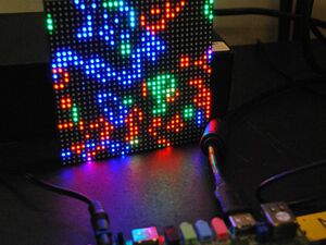
At the mid-semester snapshot da we could receive a 640x480 60 fps HDMI signal over HDMI using the HDMI2USB / Xilinx HDL. With this signal we could buffer the top 32x32 pixels of each frame and drive one 32x32 panel. We had no pulse-width modulation capabilities, however, so we were working with only eight colors. There was also a little flicker.
End Status
We got the original 2x2 panel array wired up and working, and the HDL parameterized to allow for easy adjustment to the number of panels.
The flickering has been mostly fixed (however, interlaced or scaled signals give a little bit of trouble) and gamma correction is implemented.
A very simple scaling module is working that can "divide" the input frames down by taking (for example) every sixteenth pixel without performing any kind of averaging or other scaling. This results in a passable appearance, particularly for moving images; however, there is a good amount of aliasing and the appearance of still images could definitely improve with better scaling.
Future Work
There are a number of opportunities for improvement, economization, and expansion for this project:
- ATLYS FPGA: A less expensive FPGA could probably be used.
- Panel Array: Expand the number of panels beyond a 2x2 array.
- Image Scaler: Improve the quality of the image scaling by using a more advance interpolation method on the FPGA.
- Color Correction: Improve color correction to mitigate dark banding.
- Remove any artifacts caused by excess logic delay.
- Interlacing: Detect and accept interlaced video signals, such as that from an X-Box 360.
- Make something fun: The basics are in place, so this project could be expanded into any number of HDMI LED Video projects; like an interactive game, a music visualizer, or a video cube.
Team Information
Colin Clifford - Computer Science (clif7786@gmail.com)
Peter Brown - Electrical Engineering
Document Archive
Design Failure Mode Effects Analysis
File:2014 LED Display Design Report.pdf
File:2014 LED Display Detailed Design Review.pdf
Game of Life Snapshot Demo Sourcecode
File:2015 LED Display Poster.pdf
Github Mirror: https://github.com/clif7786/led_display_files
External Links
Xilinx Spartan-A3 TMDS Application Notes
LED Panel Details (Super Useful)
