Lunar Flywheel Controls System
| UIFESS control systems | |
|---|---|
| Single-Axis Single-Bearing stabilization demonstrator | |
| Sponsors | NASA, Dr. Herbert Hess |
| Lead instructor | Dr. Feng Li |
| Mentors | David Arnett |
| Team Name | Lunar Flywheel - Controls Team |
| Duration | Fall 2016 - Spring 2017 |
The Lunar Flywheel Controls project was ongoing from 2016-2017. Our goal was to complete the stabilization and acceleration control systems.
Project Overview
In general, this team's goal is achieving precise control of UIdaho's Flywheel Energy Storage System.
Problem Statement
For a moon base to be livable, it needs a constant energy supply. Nuclear and solar power have been considered, but neither can operate constantly through both fortnight-long lunar days and nights, so some combination of technologies is required. A high-efficiency energy storage system is a desirable way to provide constant energy when it couldn't otherwise be produced, and prevent excess produced energy from being wasted. The University of Idaho has proposed the idea of using a Flywheel Energy Storage System, which can have a higher potential energy/weight density and require less maintenance than other storage options. For maximum efficiency, the proposed system features:
- An "inside-out" design with the rotor wrapped around the stator
- A vacuum chamber
- Magnetic bearings
Project History
Several teams and of work have already been done to produce the existing parts of the Low-Speed Flywheel. Continuing the work of the Fly Rollers senior design team, this year's controls sub-team works to complete the Flywheel setup and develop the embedded system to control it. Meanwhile, the Flywheel Interface Guys are developing a graphical interface for the system, and our Stator Design subteam is developing the governing equations and models needed to design a high-speed version.
Specifications
The controls team is working to:
- verify the previous progress on the Low-Speed Flywheel's control systems
- finalize the design of the Low-Speed Flywheel and get it safely working
- suggest improvements or required changes for the High-Speed flywheel
Design
Selections
Hardware choices:
- Full list:
- TI Delfino 335 Microcontroller (x2)
- TI Delfino 77d Microcontroller
- KD-2306 Eddy Current Displacement Sensor
- Resolute Absolute Ring Encoder
- 24-Volt power supply
Notes:
- Controllers
- The microcontrollers to be used were chosen/built by previous teams, but some multicore capabilities weren't utilized by the code. Optimization of the code and controller layout and setup are therefore possible.
- Sensors
- Only linear position sensors were purchased. A rotational position sensor and encoder are needed to put the whole thing together. The Renishaw RESOLUTE absolute encoder, RESA model was selected for its good resolution at our operational speeds and drift tolerances. An optical rotation sensor is necessary since there's a required air gap between the rotor and stator. An absolute rotation sensor is simpler and faster to use than the alternative of one or more incremental sensor and counting rotations.
Software choices:
- Usage of different control schemes:
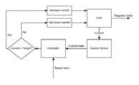
- Hysteresis/bang-bang control was optimal for the current control loop, since it minimizes the current's time to reach the SetPoint, or target value. This is optimal for stabilization responsiveness and driving coil accuracy.
- Several PID controllers are used to determine the current SPs. For stabilization, a proportional response to disturbances prevents overshoot, which is potentially disastrous. So, a SP proportional to the positional error is sent to the current control loop, which runs frequently enough that current over-correction is brief, frequent, and of minimal amplitude. This prevents current overshoot from having any net positional effect.
Details
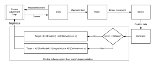
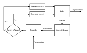
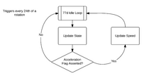
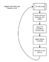
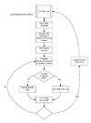
Graphs and lists of the overall system are shown below, demonstrating the evolution of the design.
|
|
|---|---|
| Hybrid PID lateral stabilization loop | PWM current control loop |
|
|
|
|---|---|---|
| Speed control loop | Position control loop | Current control loop |

|

|
|
|---|---|---|
| PID stabilization loop | Hybrid PID stabilization loop | Current control loop |
Implementation
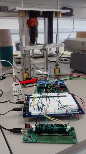
The control code is written in c, using the Texas Instruments Code Composer Studio IDE and the TI ControlSUITE package. Currently, no powered components have been used with the actual Low-Speed flywheel, but some testing of control algorithms has been done on a separate test-setup.
Testing
Control algorithm and hardware testing has been and will continue to be a major part of the project as the involved hardware is re-obtained and assembled. So far we have:
- footage of previous teams' tests.
- confirmed the MCUs (microcontroller units) and PCBs (Printed Circuit Boards) work with basic code
- found one MCU to be shorted and unusable (not a problem, we have enough spares left)
- confirmed the SASB (Single-axis single-bearing) test code compiles and runs
- confirmed the displacement sensor works, and observed how it provides output
- confirmed the SASB code can succesfully stabilize the SASB flotor!
Team Information
Group Photo
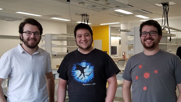
Group photo of the members of the Lunar Flywheel Controls Team in their IRIC lab.
Members
| Brian Cartwright: Computer Science |
Ian Tanimoto: Computer Science |
Andrew Jones: Computer Engineering |
|---|---|---|
| Brian is a computer scientist and humble wikimaster. | Ian is a computer scientist and algorithmic optimist. | Andrew is a computer engineer and microcontroller guru. |
