ME 430 Experiment Design
| Sponsors |
|
| Team Name | Team Icarus |
| engr-teamicarus@uidaho.edu | |
| Duration | Summer 2017 - Fall 2017 |
| Advisors |
|
| Team Members |
|
The goal of this project is to develop two experiments for the ME 430 class. These include a heat pipe and solar panel experiments. The heat pipe experiment consists of reverse engineering a heat pipe thesis by W.K. Rossiter and designing an experiment that goes with the heat pipe. The solar panel experiment consists of a solar panel that tracks the movement of the sun and a pyranometer to gather data from the different forms of solar radiation.
Solar Panel Experiment[edit | edit source]
Problem Definition[edit | edit source]
Background
Dr. Kumal Kumar wants the Capstone Design students to design two experiment platforms for the ME 430 class to use in their curriculum. For the solar panel, he wants us to make a solar tracking device that gives us feedback on how much solar energy is being produced as it follows the sun. This information would be used to generate a efficiency curve for a given solar panel.
Specifications
| Solar Tracker Specifications (As of 12/6/2017) |
|---|
Project Learning[edit | edit source]
Client Interview
- Discussed the specifications of what the solar tracker should have.
- Needs to have different Operating Modes (i.e. I-V Characteristics from forms of tracking).
- Before programming there needs to be an understanding of how the actuators determine position.
- Understand the governing equations that will be used to determine the angle of the panel.
- Budget will determine whether we have single or dual axis movement.
Lead Instructor and Technical Advisor Meetings
- Discussed our weekly issues and where we are ahead/behind.
- Discussed technical questions about the solar tracker.
- Received feedback on designs.
LabVIEW
Our team extensively researched how to program in LabVIEW to control the linear actuators of the solar panel. We will also have to integrate into our program data acquisition from the electronic programmable load.
Solar Tracker Design
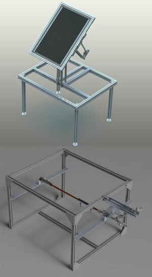
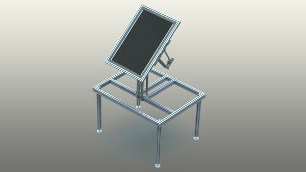
As a team sub section we researched different designs of solar trackers, in both single-axis and multi-axis variations. After finding designs we thought would work well for our application of a solar tracker. We needed a design that would work with the size of linear actuators that we chose, this way we would get the most movement out of our two axes. We decided to go with a design similar to this Progressive Automations design.
One Vs. Two Axes of Movement
Dr. Kumar taught a Sustainable Energy Sources and Systems (ME 404) that included notes on the equations that were developed to track the sun. Using these we could accurately position the solar panel for maximum efficiency. For the solar panel to follow the sun in the most accurate way we would need two axes of movement. This is way we could precisely position the solar panel's North to South angle compared to a normal way of affixing the solar panel at the appropriate angle. We were able to find a table that showed our case effectively:
Final Design[edit | edit source]
We chose this final design for a few reasons. It was able to integrate the size of linear actuators that we chose from Progressive Automations. The manufacturing process was greatly simplified with this design due to the fact that there are a few custom brackets used to put it all together. This design utilized the donated T-slot material and this was one of the ways we cut down cost.
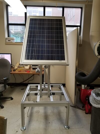
Real World Prototype
System[edit | edit source]
Complete System Schematic
Programmable DC Electronic Load
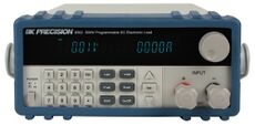
The BK Precision Electronic Load Model 8500 was selected to dissipate and read the power/voltage/current levels from the solar panel. This electronic load also works with the LabVIEW software and that makes it suitable for this project.
Solar Panel
During the initial design phase there was discussion on the capacity of the solar panel. We decided on a 100-Watt solar panel from Grape Solar because the electronic load we selected can accurately dissipate and read the load value. The solar panel also comes with a number of features that allow us to have flexibility in our design, one example is weatherproofing. We can't have an ME 430 student falling behind because of a string of rainy days.
Controller
Our controller of choice is the MyRio Student Embedded Device. This controller has 40 interfacing ports when expansion slots are included. This will allow us to control the linear actuators, detect their position, and acquire data from the electronic load with room for growth depending on our future implementations of data input devices. This controller is also compatible with the LabVIEW software that we will be using for all of our experiments.
Linear Actuators
Our chosen linear actuators were the Progressive Automations PA-14P 18 linear actuators. These actuators are weather resistant and have easily replaceable parts. They also have position feedback via linear potentiometers that are integrated in their enclosure. These features are all important to the function of our complete system.
Relay
For control of the linear actuators we decided to use a 4 channel relay board. This board switches the relays on and off when their respective pins are connected to ground. We will be using the MyRio to do this function to control the actuators.
Power Supply
The power supply for the linear actuators is a generic 12 volt, 15 amp bare power supply. This should provide enough power to the linear actuators even under maximum load.
Software[edit | edit source]
Programmable DC Electronic Load Software
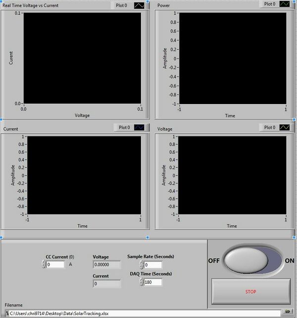
This program has a few useful features that will allow customization of the data it takes. You can see the four graphs on the front panel which show a real time voltage vs current curve, power generated, current read and voltage read. Users can control the current, rate at which the power sink runs (sample rate), and how long the dc programmable load runs (DAQ time). Users can also choose their save directory by creating a blank Microsoft Excel file and selecting that as its target file. The program then writes a file with the same name but includes a time stamp at the end of it so it looks like SampleData_yy-mm-dd_hhmm.xlsx. This was the best solution for saving data over a large period of time and easy organization.
Solar Tracking Software
The solar tracking software is accurate up to + or - 1 degree on the gamma actuator and + or - .5 degrees on the beta actuator. Now this doesn't seem that accurate but when you are moving a total of 180 degrees from East to West over a total of 8 (winter) to 15 (summer) hours it doesn't matter all that much. On average the solar panel moves a degree or two every 5 mins from East to West and and less than half a degree from North to South every 15 min. This program will allow for the manual setting of both actuators to a desired angle within the allowable range individually. This lets students choose what angle they would like to test and compare its VI characteristics of the solar panel when it is tracking the sun.
Results[edit | edit source]
| Real World Prototype | Description |
|---|---|
| This is some sample data that we took while tracking the sun on November 19th, 2017. Voltage is in volts and current is in amps. We took data over the course of the day starting at 9:30 to 2:30 on November 17th. | |
| Here is footage of us tracking the sun on the same day as above. We tracked from 11:00 to 2:30. You can also see where the camera was bumped between frames. The camera took a picture every 5 minutes to help reduce video length. |
Suggested Improvements[edit | edit source]
- Use built in filter function or use the Field-programmable gate array (FPGA) to filter out the noise from the myRIO and potentiometers instead of multiplying by 10 and rounding to the nearest tenth then dividing by 10.
- Make the junction between the solar panel and the base easier to disassemble.
- Put solar tracker on lockable wheels.
- Make a front end for the myRIO program so LabVIEW doesn't have to be started to use the integrated controls.
- Make the whole workstation easily relocated to allow for different seasons.
- Better positioning of the gamma actuator to get the most out of the 18 in stroke.
- Better positioning of the beta actuator to allow for better controls at higher angles.
- Find a solution for applying counter weights to base.
Heat Pipe Experiment[edit | edit source]
Problem Definition[edit | edit source]
Background
Dr. Kamal Kumar wants the Capstone Design students to design two experiment platforms for the ME 430 class to use in their curriculum. For the heat pipe, he wants us to build it based on a thesis by William Kent Rossiter in 1970.
Specifications
| Heat Pipe Specifications | Priority |
|---|---|
| Compatible with LabView Software | Must |
| Ability to change heat pipe and mesh (off the shelf) | Must |
| Measure heat distribution | Must |
| Measure heat flux | Strong Should |
| Tested vertically and Horizontally (possible more later on) | Want |
Project Learning[edit | edit source]
For this project we learned how a heat pipe works and what affects it. We learned what each component in the heat pipe did and how vital each of the specs were to the performance.
Client Interview
Dr. Kumar wanted to us to read up on heat pipes and how they work. One of the goals is to have a temperature distribution. Another goal was to have the heat pipe oriented in the vertical and horizontal position. Need to look up and see what thermal couples are going to be used. Need to know what is being tested for our heat pipe and have a plan for an experiment. All hardware we get must be labview compatible. Our SolidWorks model for the heat pipe is our prototype.
Lead Instructor and Technical Advisor Meetings
- Discussed our weekly issues and where we are ahead/behind.
- Discussed technical questions about the heat pipe.
- Received feedback on designs.
Testing Properties
We needed to build the heat pipe around testing the heat pipe, so we needed to research and find what were some of the most common test. Some of the test included:
- Heat distribution (really common)
- Heat transfer performance
- Fill ratio of the heat pipe working fluid to empty space
To test performance, people used R=(T_e-T_c)/Q [C/W] for the thermal resistance and h=Q/[A(T_e-T_c)] for overall heat transfer, where R is the thermal resistance, T_e is the evaporator average temperature, T_c is the average condenser temperature, Q is the power input, A is heat transfer surface area and h is the overall heat transfer coefficient. We also looked at how other people set up their heat pipe. Most of them had a heater section, an adiabatic section and a condenser section. The heaters were either a coil heater, wire heater or a block heater. Most of the experiments insulated their adiabatic section. The Condenser section was either a tube in a cooling jacket or a fin. We also had to find out how to attach our thermal couples to the heat pipe without using thermal couple wells that were permanently attached to the heat pipe.
Design[edit | edit source]
Initial Design
| Concept | Description |
|---|---|
|
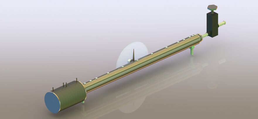
SolidWorks model of heat pipe from thesis. |
Final Design
| Concept | Design |
|---|---|
|
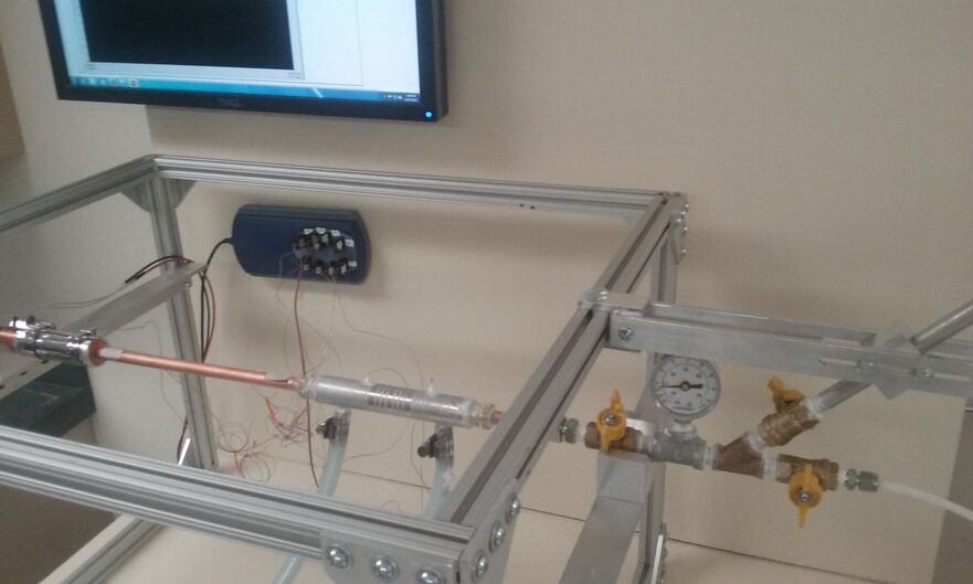
Heat Pipe set up ready for an experiment. |
System[edit | edit source]
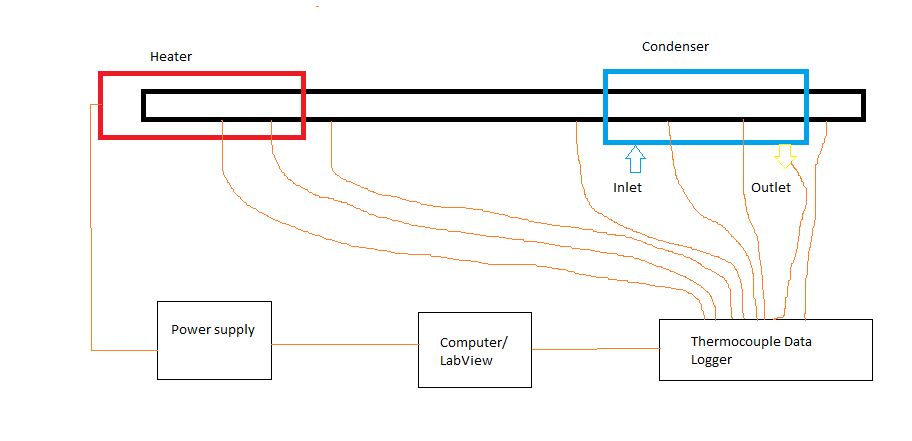
System Schematic
Heater
The coil heater will be controlled by the power supply that we can program.
Power Supply
The BK Precision 9120 Power Supply is a controllable power supply that we can control through LabVIEW. We can set it to maintain the coil heater at a constant temperature or do a series of temperatures.
Thermcouple Reader
The TC-08 Pico Thermocouple Data Logger can read the thermal couples and send the data to LabVIEW. The TC-08 has 8 channels for thermocouples.
Thermal Couples
The Sa1 Series thermal couples come with a sticky tap to attach the thermal couples to the heat pipe. They also come with a connector to plug into the TC-08.
The HSTC Series thermal couples are made to go into water. They also come with a connector to plug into the TC-08.
Operation Videos
Results[edit | edit source]
| Data Collection | Description |
|---|---|
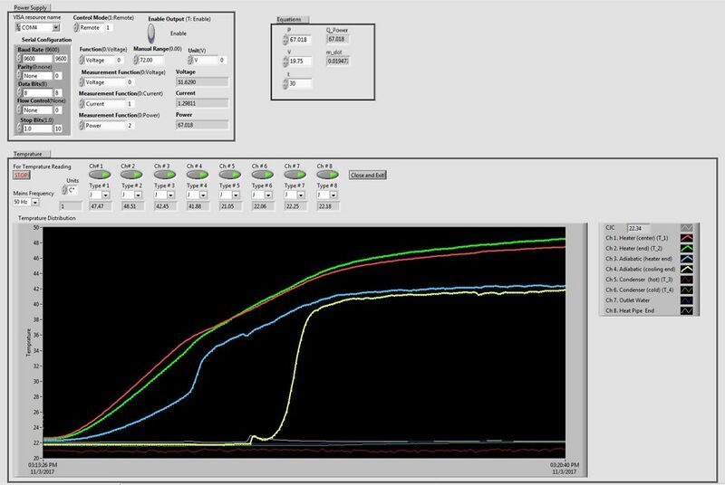
| This is the front panel of LabVIEW when taking data during an experiment. When the yellow curve sloped up fast is when the heat pipe started working. Study state began when the all the curves became horizontal. | |
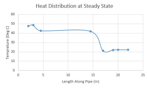
| This is the heat distribution along the heat pipe at study state for the experiment above. Notice that the adiabatic temperatures were close to each other even though they were the farthest apart. This is a good indicator that the heat pipe was working. |
Suggested Improvements[edit | edit source]
- Order swagelok weld fittings and weld them to the heat pipe and vacuum valve.
- Weld valve section together except for the connection between the vacuum valve welded to the swagelok fitting and the pipe nipple that goes into it.
- Make a secondary stand that will allow for the heat pipe to be tested at different angles.
Team Information[edit | edit source]
|
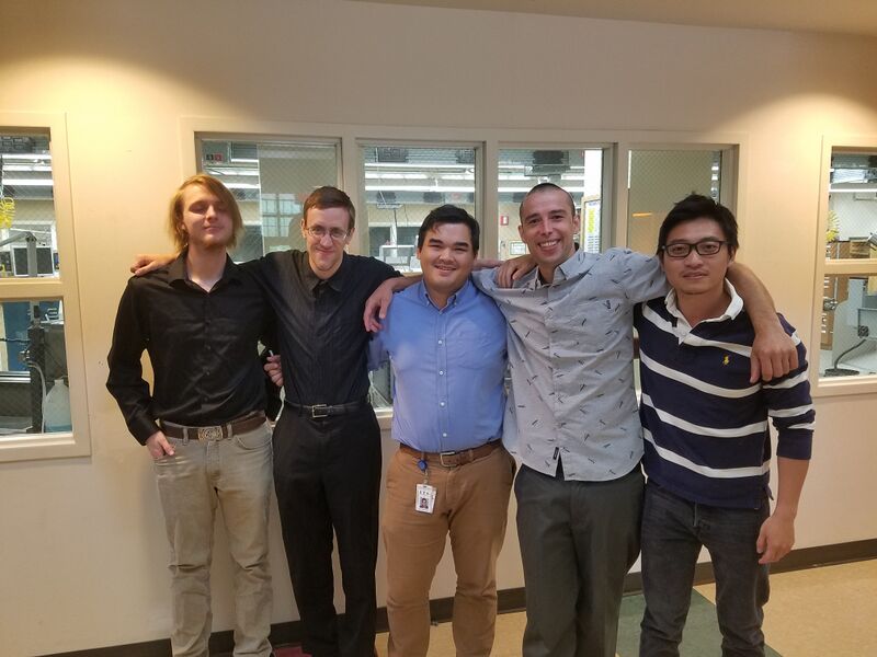
| Team members listed below from left to right |
|---|
| Daniel Cox | Project Specialty: Solid Modelling |
| Mechanical Engineering | |
| Email: cox6917@vandals.uidaho.edu | |
| Bradlee Speirs | Project Specialty: Solid Modelling, Programming |
| Mechanical Engineering | |
| Email: spei0821@vandals.uidaho.edu | |
| Jens Chrsitianson | Project Specialty: Design Development, Programming |
| Mechanical Engineering | |
| Email: chri9714@vandals.uidaho.edu | |
| Sammy Stuhlman | Project Specialty: Consultant Relations |
| Mechanical Engineering | |
| Email: stoh4463@vandals.uidaho.edu | |
| Zhengsong "Eric" Xia | Project Specialty: Scanning, Solid Modelling |
| Mechanical Engineering | |
| Email: xia6922@vandals.uidaho.edu |
Archive[edit | edit source]
File:TeamIcarus FinalPresentation.pdf
