Mastercam Chain Geometry
| Image | Step |
|---|---|
|
Right-click in the Toolpaths Manager. Select Lathe toolpaths, Rough. | |
|
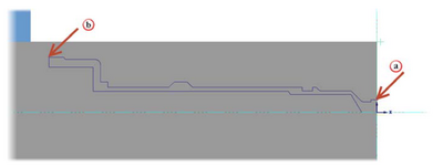
Click the geometry at the first entity and then, at the last entity to create a partial chain. Click OK in the Chaining dialog box to accept the chain. | |
|
From the Toolpath parameters tab, select the default OD roughing tool: T0101 R0.8 OD ROUGH RIGHT - 80 DEG. Type OD – Rough in the Comment field. Keep all other parameters on this page at their default values. | |
|
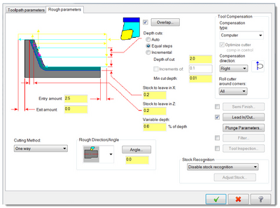
Click the Rough parameters tab. Increase the Stock to leave in X to 0.5. Select Use stock for outer boundary from the Stock Recognition drop-down. | |
|
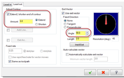
Click the Lead In/Out button a. Click the Lead out tab. The Lead in and Lead out tabs have identical options for creating entry and exit moves. This allows you to set different values for each move and to combine different types of moves. b. Select Extend/shorten end of contour. c. Extend the distance of the chained contour by 5.0 mm. Extending the distance of the part’s contour will stabilize it during the cutoff operation d. Enter 90 in the Angle field. e. Click OK to return to the Lathe Rough dialog box. Keep all other parameter on this page at their default values. Click OK to create the toolpath. Save the part. |


