Mitigating Cyberattacks caused by Fast-Acting Hardware
|
| |
| Sponsors | Dr. Saied Hemati, UI ECE Dept |
| Team Name | Transistor Biasing Dudes (TBD) |
| Duration | Fall 2017 - Spring 2018 |
| Faculty Advisors |
|
| Students |
|
This is a research based project sponsored by Dr. Saied Hemati and the University of Idaho ECE Department. The goal of this project is to design a nearly undetectable hardware trojan capable of disabling targeted integrated circuits (ICs) and developing defensive schemes to prevent a widespread flash fatal trojan attack.
Problem Definition[edit | edit source]
Background[edit | edit source]
A widespread flash fatal trojan attack may cause millions of sensitive communications, networking, computing, sensing, and/or interfacing devices to stop working and may cause enormous financial, political, or military losses. Developing techniques for eliminating security weaknesses and circuit vulnerabilities, which can be exploited in a flash fatal Trojan attack, is a high payoff and high risk research goal requiring expertise in cybersecurity, transistor physics, and mixed-signal integrated circuit design techniques.
Mission Statement[edit | edit source]
To conduct exploratory research on the feasibility of hardware Trojan attacks, and to develop suitable defensive schemes to protect vital systems.
Specifications[edit | edit source]
- Trojan must produce enough voltage to break a modern MOSFET or FINFET.
- Trojan must be able to be built within a simple, existing IC device.
- Ideally must be hidden and difficult to detect (small layout and very low power consumption).
- Trojan must be able to be activated by an external signal.
- If a device is built and validated, research will be conducted on methods to mitigate its effect.
Deliverables[edit | edit source]
Our deliverables will include:
- A functioning trojan capable of rendering an IC unusable.
- Research regarding the best defensive schemes to protect IC's against trojans similar to our design.
- A technical paper with publishable results.
Project Learning[edit | edit source]
Hardware Trojan Background[edit | edit source]
Hardware Trojan Taxonomy[edit | edit source]
Vulnerabilities[edit | edit source]
The idea behind this project is to generate a voltage large enough, that when applied to the oxide layer, it destroys it, rendering the MOSFET useless. For this, we used Cadence to simulate what these breakdown voltages will be, with schematic and simulation results shown below. These breakdown voltages are dependent on the technology used and the thickness of the oxide layer.
DC to DC Converters[edit | edit source]
Since our goal is to build a voltage up to a gate oxide breakdown level from a low input voltage, we first looked at classic DC boost converters that could be altered to complete the job. The details of these are explained below.
Inductive Boost Converter[edit | edit source]
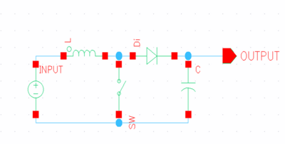
The first DC to DC converter that we looked at was the classic DC to DC boost converter.
The boost converter can generate voltages dependent on the size of the capacitor, inductor, and the switching frequency. This topic was not explored too much due to the size of inductors. One consideration was using the integrated circuit packaging intrinsic inductances, or using an off chip inductor. While this style of DC to DC converter could certainly generate the voltages needed, it would be easily identified and thus is not suited for a hardware trojan project.
Charge Pump[edit | edit source]
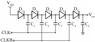
The team spent a fair amount of time exploring the charge pump, specifically the Dickson charge pump, as the DC to DC converter to boost the input voltage to gate oxide breakdown level voltages. We found, however, that we it could not handle too large of voltages without large diodes, otherwise the diodes would breakdown when reverse biased. Large diodes that would not breakdown under large voltage conditions would easily be identified from other parts of an integrated circuit.
Other Topics[edit | edit source]
On Chip Capacitors[edit | edit source]
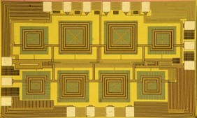
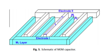
Initial project learning involved looking at many different types of on chip capacitors, such as the MOM (metal-oxide-metal) capacitor shown below. Understanding the typical values of capacitors that can be built on chip relative to their area allows us to work on a discrete build with capacitors that could be built on chip.
Transmission Gates[edit | edit source]
Transmission gates were also studied in the early project learning. Using two MOSFET transistors with gates connected, transmission gates allow voltage loss to be minimized across a transistor channel. Our initial circuit was a variant of a charge pump with transmission gates, however, we were not able to get a high enough voltage to the output before destroying the transistors of the trojan first.
Design Process[edit | edit source]
System Diagram[edit | edit source]
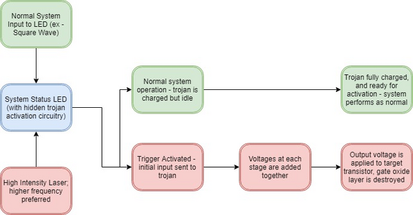
The image below shows the flow diagram of the trojan and activation complete system.
Trojan Design[edit | edit source]
There are two parts to the system design of the Trojan. The first, is the design of the Trojan itself, which produces high voltages on chip capable of rendering the chip unusable. The second is developing a mechanism by which the Trojan could be activated by an external signal.
To build the Trojan, we looked at first building a single stage that produces our desired result of increasing the voltage on the chip. After the design of a single stage, the team worked to put the stages together, where the output voltage of one stage went to the input voltage of the next, allowing us to add together as many stages as needed to produce the necessary output. The final prototype was built using 7 stages. The circuit has not been shown as the request of our sponsor.
The circuit has not been shown at the request of our adviser and project sponsor.
Triggering Mechanism[edit | edit source]
After initial project learning and discussion with professors, we decided to try to activate the Trojan using a light emitting diode (LED) as the receiver. The concept is that almost all electronic systems have status LEDs – for example, an LED that lights up when the system is on. The question we wanted to answer was, with an extra circuit discretely and secretly implemented into the system, could we send an activation trigger to the Trojan?
LEDs can work in the opposite way for which they are intended - typical use would be to put a voltage across the LED to produce light, but in fact light can also be applied to the LED externally to produce a voltage. Using a high intensity laser, and a circuit that allows us to both use the LED as a status indicator (flashing off and on), we were able to send a signal through the LED to activate the Trojan. The circuit schematic has not been shown at the request of our sponsor. Our setup uses a red LED and a red laser with an output of 3 mW. Higher frequency lasers (such as blue or green) that have larger outputs are easily obtainable and would have a better performance, but not necessary for this project with the LEDs that we are using and the budget that we have. A green LED however, would require the use of a green or blue laser to be activated.
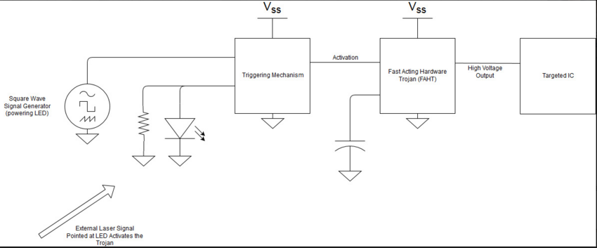
A complete system diagram is shown below.
PCB Design[edit | edit source]
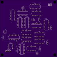
A PCB was designed using DipTrace after building the prototype using discrete components on solderless breadboards. The total size of the PCB is 4” by 4”, with two inputs (Vdd and WAVE for the status LED) and one output (Vout). The final circuit mounted on the PCB contains the following parts:
- 18 CD4007UBE packages – discrete transistors
- 7 capacitors
- 1 LM714 Operational Amplifier
- 3 Resistors
- 1 LED
- Input Port
- Output Port
Some of these, parts, including the resistors, LED, and wave input, are there to simulate the external system that the Trojan would be connected to and hidden in. The operational amplifier and one PMOS transistor are used to turn the system’s LED into an activation mechanism. Packaging for the final PCB was designed and 3D printed for our project by another senior design team, the Trailer Park Boys (see their project here). The PCB, ordered from OSH Park, is shown below.
Results[edit | edit source]
Simulation Results[edit | edit source]
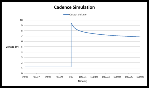
With 10 stages and simulating using Cadence Spectre, the trojan was able to produce 9.44 v from an input of 1.5 v, resulting in a gain of 6.29 v/v. This all occurred at a time of about 41.0ns after activation. This speed would be difficult for modern day electronics to detect and deter against before a vital system part was destroyed. The output voltage measurements are shown below, with activation occurring at 100.0s.
The error message below resulted from the simulation - showing that the target transistor, of same size and technology node as the trojan's transistors, will enter gate-oxide breakdown region and be destroyed, showing the success of the simulation.
Discrete Build Results[edit | edit source]
The circuit was built using discrete transistor packages, specifically the Texas Instruments CD4007UBE, and standard capacitors. These transistors are larger than what would be found on an IC device, making the activation to voltage output peak time much longer than for simulation. However, the results show that the trojan is able to be scaled - whether small transistors producing smaller voltages on chip, or large transistors producing larger voltages in a discrete system, both are able to work without the trojan being destroyed.
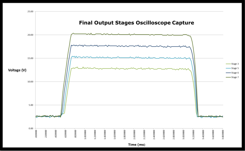
The oscilloscope capture shown below shows the output of the last four stages of the discrete build. The discrete build produces an output of 20.4 v from an input of 3.0 v - a gain of 6.8 v/v. This was done with seven different stages. The timing of this was about 120us, which is significantly larger than the simulations. As stated earlier, however, this is due to the size of the transistors.
Meeting Specifications[edit | edit source]
Upon completion of the project, we take a step back to look at the initial specifications and whether or not they were met.
1. Trojan must produce enough voltage to break a modern MOSFET or FINFET.
- Complete. Simulations show that the target transistor enters gate-oxide breakdown while the trojan itself is not damaged. Discrete build further demonstrates this.
2. Trojan must be able to be built within a simple, existing IC device.
- Complete. The circuit was created with nothing more than transistors and capacitors, which are easily implemented on chip, unlike other common components, such as inductors or resistors.
3. Ideally must be hidden and difficult to detect (small layout and very low power consumption).
- Complete. One stage contains a capacitor and 4 transistors, which would easily be hid on a chip with thousands to hundreds of thousands of transistors. Stages can continuously be added on to produce a voltage needed to destroy the circuit.
4. Trojan must be able to be activated by an external signal.
- Complete. A voltage high applied to the the switch triggers the trojan. We were able to use an LED as a receiver for an external signal.
5. If a device is built and validated, research will be conducted on methods to mitigate its effect.
- On going. the device has been built and validated, although with little time to spare conducting research on how to mitigate its effect.
Future Work[edit | edit source]
This project was started from the beginning this semester, and finished within the academic year. The team is currently exploring opportunities to present their design and findings in journals or conferences. Rafael Watanabe will be pursuing graduate studies at the University of Idaho, and may continue writing papers on this subject.
One of the initial goals of the project was to have the trojan fabricated on chip by MOSIS and packaged. Continuing with this and making a chip, instead of building using discrete components, would be an interesting and useful continuation of this project.
Documentation[edit | edit source]
Further Documentation is shown here.
Expo Poster (schematic not shown)
The Team[edit | edit source]
| Member | Discipline | ||||
|---|---|---|---|---|---|
| Hector Cruz | Electrical Engineering | ||||
|
Hector grew up in Boise, Idaho. His academic interests include microelectronics and power electronics. Outside of school, he enjoys just being a dude. After graduation, he plans on becoming a hard working engineer in the workforce. | |||||
| Dustin Mallett | Electrical Engineering & Applied Scientific Modeling Mathematics | ||||
|
Dustin was born and raised in Idaho Falls, Idaho. His academic interests include electronics and communication systems. Throughout his time at the University of Idaho, he has served as a lab assistant for the Circuits I lab and as President of the ECE Ambassadors organization. Outside of school, he enjoys playing hockey and woodworking. After graduation, he is moving to Orlando, FL, to be a Systems Integration and Test Engineer. | |||||
| Brenton Van Leeuwen | Electrical Engineering | ||||
|
Brenton grew up in Kuna, Idaho. His academic interests include microelectronic design and semiconductor devices. Outside of school, he enjoys playing on the University of Idaho club lacrosse team. After graduation, he is moving back to Boise to be a DRAM Product Engineer at Micron Technology. | |||||
| Rafael Watanabe | Electrical Engineering & Applied Scientific Modeling Mathematics | ||||
|
Rafael is from Aguas Claras, Brazil. His academic interests include microelectronic design and power electronics. After graduation, he intends on continuing towards a masters degree here at the University of Idaho with a focus on power electronics. | |||||


