Modeling and Measurement of Permittivity for Near Space Communications
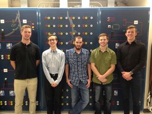
| Team Photo
From left to right: Brett Morris, Jeffrey Craig, Ryan May, Cameron Murdock, Benjamin VanSant | |
| Sponsor | Dr. Zadehgol |
| Mentor | Dr. Li |
| Team Name | NASAE |
| Duration | Fall 2017 - Spring 2018 |
Team NASAE, Not your Average Socially Awkward Engineers, is designing a circuit and package that can measure the permittivity of the air, as altitude changes, between ground level and 100,000 feet (near space).
Project Overview[edit | edit source]
Problem Statement[edit | edit source]
Our mission is to make new and exciting discoveries by designing, fabricating, and testing new devices to collect and analyze information about near space. The information to be measured is a quantity known as permittivity which describes a substance’s ability to resist an electric field. In order to measure permittivity in near space, aspects such as temperature, humidity, and signal frequency will need to be taken into consideration for accurate data collection. It is desirable to then plot this quantity with respect to time and position.
Project Goals[edit | edit source]
Mechanical Engineering Design Goals[edit | edit source]
Create a functional package (housing) for the electrical components to work and collect data properly. Model/Simulate forces, temperature, and other conditions on payload and package. Ensure that the payload will return to ground safely without affecting any of the packages inside. Find a material that will insulate our electric components to function at certain temperatures that will not interfere with data recording. Allows airflow to measurement devices. Allow component to work in different environments.
Electrical Engineering Design Goals[edit | edit source]
The goal of this project is to measure the permittivity of the air, from the ground to near space. We want to send a payload to near space, one hundred thousand kilometers, while measuring the permittivity as it goes up. At the very least, we will simulate this behavior using circuit design software. Permittivity: the ability of a substance to store electrical energy in an electric field. Basically, we want to measure the resistance of the air has to an electric field, or how long it takes for a charged particle to get from point A to point B. We will do this by transmitting a signal between two antennas and measuring the received power. Using the Friis Transmission Space Loss equation we can relate the ratio of power received to permittivity, and from there determine the permittivity of the air at discrete points in the atmosphere.
Conclusion[edit | edit source]
Our final goal for this project, to measure permittivity, was not met. The reason we were unable to meet our original goals is because we were unable to initialize both of our antenna. After testing one antenna successfully, we rebooted the board and code, but were unable to initialize either of our other identical antennas. Due to time constraints we were unable to solve this problem or get new antennas. Theoretically our package will be ale to measure permittivity assuming future teams can get their antennas functional.
Project Problems/Solutions[edit | edit source]
Concept Selection[edit | edit source]
The selected design was based on the ability to measure variables of importance with some degree of accuracy, the cost of the system, and ease of achieving the measurement of permittivity. The capacitor method would have been the easiest to implement. However, the accuracy of this system would be dependent upon our ability to measure capacitances smaller than 1 pF with an accuracy of at least 0.01 pF. This would require a very accurate measurement scheme that would be relatively costly. The boundary condition method would be complicated to implement in that various reflections that are not oblique to the dielectric would result in inaccuracies in the data that would have to be accounted for. The cost of such a system would only be a little bit more than the antenna system in that the only thing being added is a dielectric. The laser system would be very accurate if more space was available. The complexity of this system is variable. If the laser system were to be designed in its entirety, this would be a very involved design. On the other hand, if an off the shelf laser was purchased, the design would be simplified immensely. However, off the shelf accurate laser measurement systems by themselves range from $500 - $30,000 which is a little bit too costly. The antenna system was the most viable in that the variables being measured could be measured accurately with non-expensive parts. The implementation of this design wasn’t going to be easy but it wasn’t going to be too hard either. The hardest thing was going to get the antennas to communicate. After realizing a budget, this was the design that we decided upon for we thought it to be the most feasible solution.
All the discussed methods are detailed below.
Antenna Method Design[edit | edit source]
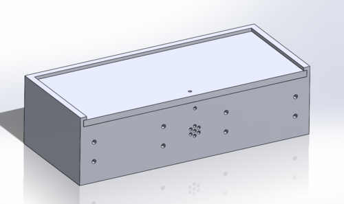
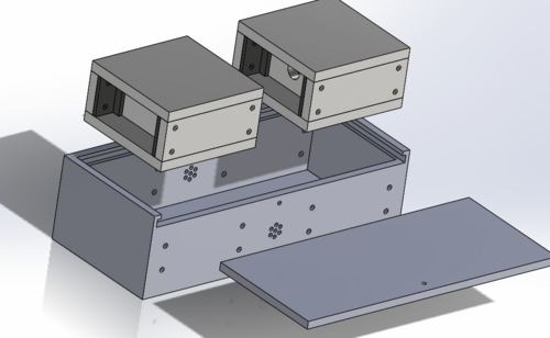
Due to the harsh environment the electrical components will be subjected to at high altitudes some protective measures needed to be taken. During a flight the components would be subjected to extremely low temperatures as well as an impact at the end of the flight. A protective housing was necessary in order to protect the components and allow them to function correctly during the flight. The antenna method also requires that the antennas are held a minimum distance away from each other so all communication is done in the far-field region. The housing created in order to meet these requirements was created.
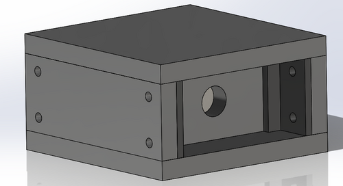
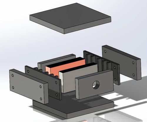
The outer shell of the housing is made of ¼” birch wood that was cut into pieces using a laser CNC machine. The pieces were fixed together using a high strength wood adhesive. Inside of the shell are two identical units. Each unit has a layer of aluminum foil tape lining the outside and a layer of ½” polyethylene insulation. Inside of the layers of insulation there are two plates that were 3D printed out of HIIP plastic. These plates are used in order to keep the electronic components, heat source, and several layers of insulation in their proper places. Each unit is fixed to the shell using four ¼-20-1.25” bolts and the appropriate nuts.
The benefits of two seperate units is that the heating that was required could be focused into smaller areas which allows for a smaller, less powerful heat source to be used. The antennas need to be exposed to ambient temperature and pressure in order to get the most accurate readings possible so the center of the enclosure was left with several holes in it to promote equalization with the atmosphere. Future teams might want to look into finding more reliable heat sources in order to ensure proper heating for the duration of the flight. One other benefit of having the insulation units is that the insulation provides some cushioning during impacts along with the styrofoam container that will contain our housing and other components from other groups. The units are spaced out in order to ensure that the antennas are well into the far-field region and will function properly. In our antenna system, we are measuring the the power received, and transmitted, between two points. With this data, we can calculate the permittivity of the air. To continue development, future teams will be able to take this starting point, and truly measure permittivity. With where we are currently, we theoretically can measure permittivity, using just two antennas. Whoever picks this project up will just need to get the antennas to work correctly.
The electrical structure needs to do multiple things. First it has to be able to measure permittivity, this is done through the antennas. By spacing them a set distance d apart, with the mechanical structure, and recording the internal power measurements from the transceiver modules we are able we can calculate the phase velocity of the signal and from there the permittivity of the free space between the antennas. Second, we want to be able to record the ambient conditions to see how they are affecting the permittivity, to do this we are measuring temperature, pressure, and location. The below schematic details the connections between the our microcontroller, the Teensy 3.6, and the various sensors and one of the transceiver modules.
This schematic details connections for proposed circuit design with one transceiver module connected. All ground, 3.3V, and Vin pins are labeled as nets to reduce number of wires necessary, but are physically connected in the actual design. Many pins on Teensy serve multiple functions, so layout can be adjusted as needed for future components if desired.The second transceiver module is not shown here, it will be connected to different pins on the Teensy that have the same functions as the connections shown below. The power supply is not shown in the schematic, but the batteries will supply 5V to the Vin terminal of the Teensy and pressure sensor. All measurements recorded during the flight will be stored on a Micro SD card housed on the teensy.
The Package[edit | edit source]
Mechanical Analyses on the Package[edit | edit source]
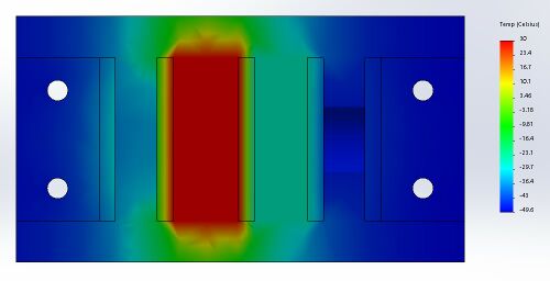
Thermal Analysis
Pictured to the right is a thermal analysis on the package that will be surrounding the circuit boards we create. This package will keep our electronics warm enough to operate during the flight. The circuit boards will be kept at about 20 °C, even at 100,000 feet.
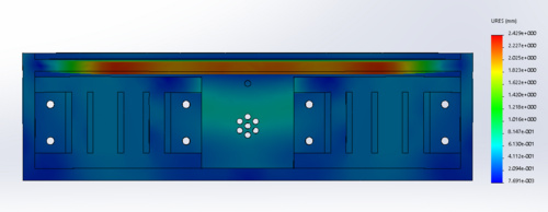
Displacement Analysis
Displacement Analysis of forces acting on top moving downward the box.
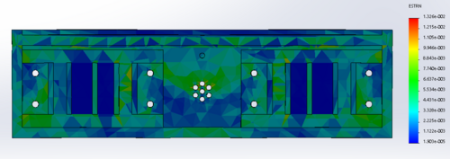
Strain Analysis
Strain Analysis on Box as Forces Acting Downwards on top of the box.
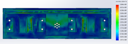
Stress Analysis
Stress Analysis on Box as Forces Acting Downwards on Top of the box.
Project Learning[edit | edit source]
Methods for Measuring Permittivity[edit | edit source]
Antenna Method[edit | edit source]
The layout of this method consists of a transmitting and receiving antenna system that are separated by a constant distance. This scheme could be used in a similar way as the laser method in that the time it takes for the signal to go from the transmitting antenna to the receiving antenna could be stored and with the antenna’s being a set distance apart, the speed of light can be derived. As with the laser method, this setup would have similar issues due to the inability to clock fast enough. Other than improving our clocking rate, this method of measuring permittivity could be possible if we had a larger distance between the two antenna. Because we have a fixed space within the package we would have to use one antenna on the ground and one antenna on the package. We would then be able to measure much larger distances and get accurate readings for permittivity with the same clock speed. In order to ensure we are not simply measuring the average permittivity of the free space between the two antenna we would have to gather the data and then use a recursive equation solving method and the differences in the time it takes the signal to reach the ground. The issues with this method are that we would need higher gain antennas to transmit over the increased distance and we would need to have clear line of sight between the two antennas for the entirety of the flight. Rather than measuring the time it takes for the signal to travel from the transmitter to the receiver in order to calculate the speed of light and then permittivity, the Friis Transmission Space Loss equation allows for the derivation of permittivity as follows:
- <math>\frac{P_r}{P_t} = \left( G_r G_t(\frac{\lambda}{4 \pi d})^2 \right )</math>
or
- <math>\frac{P_r}{P_t} = \left( G_r G_t(\frac{c}{4 \pi f d})^2 \right )</math>
This relates the transmitted and received powers, the gains at the transmitting and receiving antennas, the frequency of transmission, the distance between the antennas, as well as the speed of light from which permittivity can be derived! In order for this equation to be relevant, the receiving antenna must be in the far field region of the transmitting antenna. This distance is determined from the following relation:
- <math>d \; = \; {{2 D^2}\over{\lambda}} \,</math>
Accuracy in this design is dependent upon the ability to measure the power at each antenna, the capability to keep the distance between the antennas constant and far enough away as in accordance with the far field requirements, as well as acquiring accurate information provided by the antenna datasheets.
Capacitor Method[edit | edit source]
The first method we designed to measure permittivity was to use a parallel plate capacitor. By using free space as a medium. By knowing the dimensions of the parallel plates and then measuring the capacitance we could directly relate it to the permittivity of free space using C=ϵ A/d. The problem with using this method is due to its inaccuracy at high frequencies. To measure the capacitance we would send a square wave with a period long enough for the capacitor in a series RC circuit to charge. Knowing the value of the resistor and the time it takes for the voltage to be 1/e (37%) of its maximum value we could then find the time constant of the circuit, from which we could get the capacitance. Unfortunately with this method the rise and fall times of the square wave source, when at the desired high frequencies, are no longer negligible. This leads to distortions in the discharge rate which leads to an inaccurate measurement of the capacitance. Because the goal of this project is to characterize permittivity at high frequencies we decided not to use this method.
Laser/Phase Velocity Method[edit | edit source]
The use of this system exploits the derivation of permittivity from the speed of light. With this system, a laser source would be used to generate laser pulses to be sent to a reflective object. The laser signal would be reflected back to the laser source where there is also a receiver. The time for this transmission would be clocked and with the distance between the laser and the reflective object constant, the speed of light can be calculated through the following development: vp = 𝑐/sqrt(μ𝑠*ε𝑠), where d is the distance between the laser and the reflective object, t is the time it takes for the laser to go to and reflect back from the object, ε is the permittivity, and μ is the permeability which can be assumed to be 1. One of the downfalls of this method is that accurate laser transmit and receive systems are costly. Also, in order for this to be a viable and accurate system, the distance between the laser source/receiver would have to be far enough apart such that the speed of the laser transmission can be clocked. In other words, this distance, would be dependent on how fast of a clocking rate the data acquisition scheme had. For instance, if a 100 MHz clocking rate was available, the period would be 10 ns. With the speed of light at about 3x10^8 m/s, the distance light would travel in 10 ns is 3 meters. So the distance of separation between the laser and the object should be at least 1.5 meters. Increasing this distance or increasing the clocking rate would increase accuracy. Considering we were confined to an area of about 30cm by 30cm, we would have to have a considerably high clocking rate to make this an accurate setup which further increases the design’s cost. If more space was provided however, this may be a fairly accurate scheme. Also, considering laser signals are usually in the infrared spectrum, the frequency range for such a system could vary from 300 GHz to 450 THz!
Boundary Condition Method[edit | edit source]
This method takes advantage of the reflections that occur at dielectric-dielectric boundary. By placing a thin sheet of material with a known dielectric between two antennas communicating across free space we could measure the incident, reflected, and transmitted power. From these we would be able to relate the permittivity of the free space to that of the medium. The issue with this method is that in order to eliminate incident angles the thin sheet would have to be perfectly orthogonal to the propagating wave, in practice this is difficult to achieve.
Team Biographies[edit | edit source]
Benjamin VanSant[edit | edit source]
Mechanical Engineering Student
Hometown: Stanwood, WA
Hobbies and Interests: I love being outdoors and being active. Soccer, rock climbing, mountain biking, and snowboarding are a few of my favorite activities. I am interested in motorsports and racing. Someday I would love to find a job in that field, designing (or driving) high end cars or motorcycles.
Future Plans: Next year I will be entering the workforce. I am planning to move to either the Puget Sound area or southern California to find a design or manufacturing job which will give me the opportunity to grow as an engineer.
Email: vans6909@vandals.uidaho.edu
Brett Morris[edit | edit source]
Mechanical Engineering Student
Hometown: Oakley, CA
Hobbies/Interests: I am interested in how things work in mechanical systems and how they are designed. I always thought it was fascinating how people created 2D objects and transformed them into 3D models using CAD and other programs. Some of my hobbies are; snowboarding, video games, hanging out with family/friends, and sports.
Plan for Future: Pass the Fundamental Engineering exam as soon as possible and then start working towards passing the Professional Engineering exam. I would like to live and work in the Pacific Northwest.
Email: morr7547@vandals.uidaho.edu
Cameron Murdock[edit | edit source]
Electrical Engineering Student
Hometown: Laclede, ID
Hobbies/Interests: In general, my interests involve understanding how various systems work and how to improve those systems. In the field of Electrical Engineering, my interests include signal analysis and control theory. In my free time, I enjoy learning about new technologies and exploring the outdoors.
Plan for Future: As of now, I am not set on a particular path. I may go on to graduate school at Montana State University in order to study photonics so that I can eventually work at Bridger Photonics which is a company where I was an intern over the Summer of 2016.
Email: murd7115@vandals.uidaho.edu
Jeffrey Craig[edit | edit source]
Electrical Engineering Student
Hometown: Enumclaw, WA
Hobbies and interests: I am interested in technology in general. I like to build models, draw, and play videogames. It is fascinating how fast technology is growing, take the Nintendo Switch for example, it is so innovative. I have been involved with many engineering related clubs on campus, including IEEE, IMAPS, and ECE Ambassadors. Working on electrical projects on the side is also pastime of mine, I recently build a board that lights up with LEDs.
Plan for the future: After graduation I would like to work in the Seattle area. I have worked for the same company the past two summers, and would like to work for them again, in the avionics industry. It would be fun to eventually end up working for Nintendo though.
Email: crai5936@vandals.uidaho.edu
Ryan May[edit | edit source]
Electrical Engineering Student
Hometown: Boise, ID
Hobbies and interests: I am interested in communication systems as far as electrical engineering goes, I am also interested in science in general. Since my freshman year I have been involved in a research lab in the biology department investigating how transmissible vaccines could improve how we combat viruses in both epidemic and endemic situations through mathematical models. My hobbies include video games, mountain biking, and skiing.
Plan for the future: After graduating I plan to pursue a career involving communication, ideally working either with satellite communication or radar with ships and submarines.
Email: may6552@vandals.uidaho.edu
Files[edit | edit source]
Meeting Minutes[edit | edit source]
Data Sheets[edit | edit source]
These are the data sheets for the main parts that we used.
Antenna: DWM1000
Teensy 3.6
Microcontroller (On Teensy)
GPS
Pressure Sensor
Temperature Sensor
