|
|
|
|
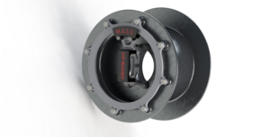
| Early Design Concept
|
| Sponsor
|
|
| Team Name
|
M.E.S.S.
(Mechanical and Electrical Stopping System)
|
| Duration
|
Fall 2013 - Spring 2014
|
| Faculty Advisers
|
|
| Mentors
|
- Giselle (Jaz) Veach
- Jon Teske IEW
|
| Students
|
- Micah Wilson
- Tate Bischoff
- Jay Nair
- Victor Zarate
- Chinmay Subedhar
|
Our purpose is to design mechanical and electrical braking for the new all-electric formula electric vehicle. The vehicle will be powered by in-hub linear induction motors. We are also designing motor housing, bearings, and an apparatus for testing. Ultimately the vehicle will compete in the Society of Automotive Engineers (SAE) all-electric vehicle competition.
Design Task
Jaz Veach, a graduate student in the electrical engineering department is currently designing in hub motors for an all electric vehicle. The motors will be using linear induction motors as the wheel as well as the drive system which will be more efficient than a conventional internal combustion engine and drivetrain. Because the only rotating part of the motor is the rim, braking and connecting the motor to the car is difficult.
The electrical engineers are designing and building regenerative braking system as well as a battery charging system for the vehicle.
The mechanical engineers building a motor housing, a mechanical braking system, and a stand to be used to test the motor and braking.
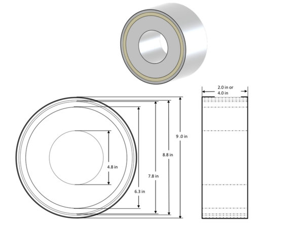
Linear Induction Motor (LIM):
- Rotating rim/rotor
- Static center/stator made of laminated metal plates with fins and wire coils wrapped around the fins
- Projected operating speed (straight line) - 35mph
- Projected power - 25hp
- Inside diameter - 4 inches
- Outside diameter - 9 inches
- Width - 4 inches
Given LIM Dimensions:
Design
Objectives
- Mechanical Braking
- The vehicle must be able to stop the vehicle in a reasonable amount of time
- The brakes must be able to lock up the wheels at speeds of ~40mph in competition
- Regenerative Charging
- The motors should be able to act as generators to save energy as the vehicle is braked electrically
- The system should be able to charge the batteries from 120 VAC 240 VAC and 500 VDC
- Wheel Attachments
- The wheel attachments should be able to take the force of the motors as well as the weight of the vehicle
- The wheel attachments should be easy to attach to a test apparatus as well as the suspension of the vehicle
- The rim of the wheel should be removable to accommodate for wet or dry tires at competition
- The wheel/motor assembly should be as light as possible and less than 40lb
- The wheel attachments must be able to serve as a bracket for the brakes
- Test Apparatus
- The test apparatus should be able to simulate the LIM
- The test apparatus should be able to accurately measure braking forces under reasonable loads
- The test apparatus must be able to handle loads without failing
- Bearings
- The bearings must be able to keep a clearance between the stator and the rotor of the LIM
- The bearings must be able to hold the rotor on the stator given side to side dynamic motion
- The bearings must be able to handle ~1000lb static loading
Concepts
Design concepts to fit the objectives:
| Objective
|
Concept
|
Pictures/Models
|
Rationale
|
| Brake Caliper |
Yamaha R6 Brake caliper |
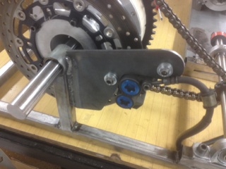 |
Our design allows for a stock brake caliper and disc. We had already purchased a cheap set of R6 calipers for a different design. The calipers should be more than able to lock the wheels of the vehicle under speeds up to 60mph. We tested the brakes by spinning our housing with a 2hp DC motor. Our brake stopped the motor within 5 seconds. We can test the motor to find its stall torque and we will have some idea of our braking power.
|
| Brake Disc Assembly |
Yamaha R6 Brake disc and attachment |
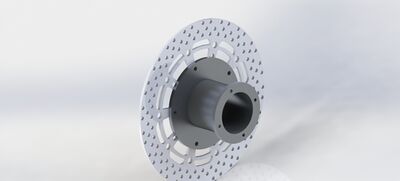 |
We used a stock brake disc, and built an assembly out of Aluminum to connect the brake disc to a dynamic wheel center.
|
| Dynamic Wheel Center Assembly |
Rotating disc that attaches the rotor to bearings |
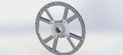 |
The rotating wheel centers attach the wheel to the static shaft. This makes it possible to use stock bearings. The wheel centers take the load off of the motor and onto the static shaft. There will be a dynamic wheel center on each side of the motor to balance loading.
|
| Static Wheel Center |
Static shaft and bracket to hold the stator |
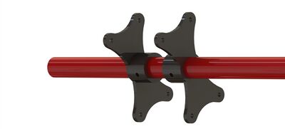 |
The static wheel centers connect the static shaft to the rotor, and hold the motor in the wheel. There will be one on each side of the motor to balance loading.
|
| Test Stand |
Chain Drive |
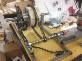 |
The motor stand has a second shaft to connect to either a water brake dynomometer or an electric motor. The shaft spins the motor housing apparatus to simulate the in-hub motor. This allows testing of the motor housing and brakes without the in-hub motor. The wood is a mock-up of where the motor will be placed.
|
| Wheel |
Keizer Wheel Barrels |
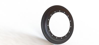 |
Our design is to use two outside wheel barrels from a three-piece wheel. The tire will fit between the barrels over the outside of the rotor. Due to funding concerns we will not be purchasing these for our prototype. But our design is such that they can fit the assembly when they are purchased at a later date.
|
| Rapid Charger |
The battery charger design modified an open source design by Electric Motor Werks (EMW) |
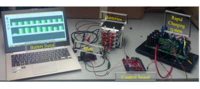 |
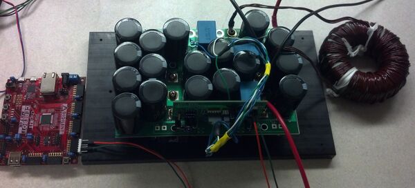
The input voltage can be 120VAC, 240VAC, or up to 500VDC. The input voltage can then go through a buck or boost circuit configuration. The pic32 controller controls the PWM for the buck or boost to control the voltage into the batteries. The battery management system (BMS) a design by a previous senior design project controls the cell balancing as the batteries charge.
|
| Charging Circuit |
Flow Chart |
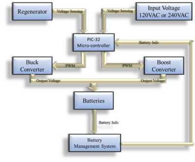 |
Flow of the charging circuit.
|
| Regenerative Circuit |
The regenerative circuit was designed by a previous project |
 |
Our purpose was to build a MATLAB Simulink model of the regenerative circuit.
|
The Final Product
Our final deliverables were a rapid charger for the existing battery system, motor stand and housing, and mechanical braking. These are all pieces that are required to test the in-hub motors when they are built (summer 2014).
Full Assembly Model
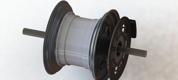
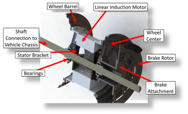
Our full assembly renders from SolidWorks. The full assembly includes the wheel barrels even though we were unable to purchase them.
Full Assembly:
Full Assembly Cutaway View:
Stand
The motor will go where the wood cylinder is, and the small shaft will connect to a water-brake dynamometer. This video shows us proving the stand and braking capabilities with a DC motor connected to the small shaft.
Rapid Charger
Charging circuitry:
Team Members
 |
Micah Wilson
Mechanical Engineer |
Micah is a mechanical engineering major. His interests are in dynamic systems modeling and control. He has been an active member in the ASME (American Society of Mechanical Engineers) at the University of Idaho, including holding a position as the club treasurer. He is also active at Idaho as a campus leader in the Christian campus group Cru (formerly Campus Crusade for Christ). Micah interned for the Boeing Company in summer 2011. In addition, he enjoys playing guitar, fishing, hiking, and playing sports in his free time.
|
 |
Tate Bischoff
Mechanical Engineer |
Tate is a mechanical engineering major. He is an active member in his fraternity Alpha Kappa Lambda where he has held many different board positions. Tate is also a member of the University of Idahos Men's Club hockey team. Some of Tate's hobbies include hunting, fishing, hiking, skiing, and anything outdoors.
|
 |
Jay Nair
Mechanical Engineer |
Jay is double majoring in mechanical engineering and applied physics. He is an active member of Tau Beta Pi at the University of Idaho and is a past president of the club. He is also an active member in his fraternity, Phi Delta Theta, where he has held various executive board positions. In his free time, Jay enjoys reading and playing a variety of sports.
|
 |
Victor Zarate
Electrical Engineer |
Victor is majoring in Electrical Engineering. His interests are in power electronics, control systems, and signals and systems. He is a student member of the IEEE, and SHPE. Victor enjoys playing soccer and participating in recreational intramural team sports.
|
 |
Chinmay Subhedar
Electrical Engineer |
Chinmay is majoring in electrical engineering. His interests are in power systems, protection system analysis and PCB design. His extracurricular interests lie in F1 racing, swimming and badminton. He has been a member of Indian student’s association since 2010 and was also the President of the same for the year 2011-2012.
|
Document Archive

