Persistence of Vision Machine
| Persistence of Vision in Action | |
| Client: |
|
| Team Name: |
|
| Faculty Advisers |
|
| Team Members |
|
Persistence of vision (POV) refers to the optical illusion whereby multiple discrete images blend into a single image in the human mind and believed to be the explanation for motion perception in cinema and animated films. Like other illusions of visual perception, it is produced by certain characteristics of the visual system (link). Our objective is to build a large display by taking advantage of POV using precision activated LEDs and rotational mechanics.
Problem Definition[edit | edit source]
The University marching band is aiming to improve their halftime shows using LED based devices, and requires a large, low cost display that is both entertaining in form and execution of display content.
Project Requirements and Goals
- The diameter of the visual display should be at least two meters.
- Capable of maintaining rotational speeds necessary for POV.
- The machine should be weather resistant.
- It should not require more than two people to transport safely.
- The electronics should not require any external power sources.
- LED colors should be capable of University theming.
- Display content should be programmable by anyone given instructions.
- The display's on-time should be at least 10 minutes in duration.
- A single POV machine should cost around $250.
- Write instructional documentation to assemble a POV machine.
- If possible, build five POV machines to display the word "IDAHO".
Background[edit | edit source]
Currently, the University of Idaho marching band has been using LED electronics to improve their half time shows. As their performances become more extravagant, so do their LED props. Our task is to build a visual display using ordinary LEDs that boasts an entertaining design. POV is particularly elegant in this respect, as it can provide an avenue of visual entertainment without using a typical store bought display. The project will implement the concept of POV by spinning a strip of LEDs in a circular motion at high speeds. The rotational movement combined with precision blinking of LEDs creates a visible image, similar to a regular TV screen. This design however is much cheaper, more robust, and a unique display of entertainment. Our objective will be to create five 6' diameter POV machines. These machines will be used by the University of Idaho Marching Band for the purposes of halftime football game performances to display entertainment content.
Project Learning[edit | edit source]
As our project progresses in development, we solve one problem after another. The following is a categorical breakdown of the project learning for each major conceptual milestone.
Mechanics[edit | edit source]
The evolution of the mechanics of this project have progressed rapidly over each iteration. The objective is to have a light, portable, cost effective, and safe design. The following are three major design approaches, and the last being the most successful and the one chosen to be implemented.
- Design Iteration I
- One of the more important design concepts is safety and stability. This is possible by confining the rotational assembly to a guided track. Using this approach is an attempt to achieve both as effectively as possible by trapping all potentially dangerous components within the track. However, due to cost constraints and mechanical difficulties it was discontinued
- Design Iteration II
- To combat the issue of cost while maintaining stability, a new concept of spinning flexible stiff strands that house the LED strips was introduced. This concept no longer needed any large supporting structures, was highly transportable, and was cost effective. Essentially, it was an attempt at a giant glowing weed-eater. Due to safety constraints and a failed prototyping process, this concept was discontinued.
- Design Iteration III
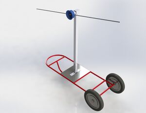
- Somewhere in the middle was the idea of having a simplistic motor securely mounted on a hand dolly. Attached to the motor is a hub that houses any electronics, and on the hub are two spokes. Each spoke would support its own strip of LEDs. This concept was moderately cost effective, simple to replicate and assemble, and stable. To enable some level of safety precaution, rounded tubing is used rather than sheet metal. Furthermore a hand drill is used as a motor for several reasons. It uses a ratcheting system that sets the tension on a clutch, so if someone where to be struck by the spokes the motor would not continually apply force after the strike. Next, it provides its own electronics package and is easily replaced. Finally, it's extremely cost efficient by comparison with a custom package. The following is an image of this design concept.
- Design Iteration IV
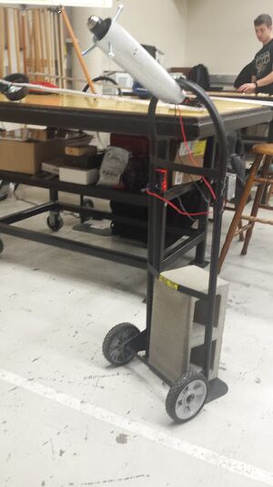
- The dolly system was good, but not quite stable enough. Furthermore, we were still pushing the limits of our budget per machine. To solve these problems with our third design, we decided to move the motor's mounting location, and remove it's supporting beam entirely. Instead of laying down during operation, the machine would operate while the dolly is standing upright. The motor is mounted at the top, removing the need and cost of a large metal beam. There was a need to add a counterweight to prevent rocking motions, which we would have likely needed regardless of version, and conveniently because of the way a dolly do we can simply add a cinder block.
Electronics[edit | edit source]
LEDs and Imaging
There are two main ways to display an image using persistence of vision. Both have useful applications and will be implemented at the convenience of the end user. The difference mostly comes with the preparation of the source image and its manipulation, as well as the desired end result. There is a third, and though it's superior to both of these methods, it requires floating point operations that are too slow for the micro controller we have been limited to.
The LEDs we decided to use were Adafruit's DotStar strips. They clearly stated that they are capable of similar POV applications, and are quick to address. This made them a much more suitable choice over strips known to be far too slow for POV, and over building our own strip due to our computer engineering skills limitations.
- Imaging Display I
- Direct image display typically results in a warped image. This is often used to display clocks and character based information. The content is physically wrapped around the display and in relation to the center of the wheel. Images are often described as donut shaped. If an image were displayed above the center, it would mostly appear normal. If it were displayed below the center, it would be flipped upside down. This is because of the nature of displaying quadratic pixel coordinates using a polar coordinate system. The following is an digitized example of how a regular full sized image would look if applied to the entire display. Though very distorted, displaying text around the perimeter of the wheel is fairly tangible and easy to read.
- Imaging Display II
- Polar converted display produces an image that can be sized to fit the entire display without the consequence of warping or reversed content. Getting this kind of image requires modifications to the source file. The basic concept is to treat a given image as if it were already drawn in polar coordinates, translating it to rectangular using a program such as Photoshop or Gimp, and then allowing the illusion mechanics of the wheel's rotation to translate the image back into polar. This process involves scaling an image to at least 360 pixels wide and tall, warping its coordinates into a polar state, scaling the image's height down to the number of LEDs per spoke, reducing its color into a palette 1 or 4 image, and then exporting it. Once done, the image can be displayed relatively clearly and across the entire POV machine's display. The following depicts this process, and the third image is what is displayed by the POV machine when the rotational mechanics' physics translate back from the fourth image. The drawback is that the image must at least be 360 pixels wide to compensate for at least 360 degrees of updates in one rotation. This makes the image size almost too large for our micro controller, and divides images into 1 degree slices which can look somewhat out of place on a still image.
- Imaging Display III
- On the fly conversion display produces the most clear image possible, while preventing any need for Photoshop like programs. Though, because of the floating point calculations needed to achieve this method, our micro controller prevents us from using it due to speed limitations. If we had used a Teensy or Raspberry Pi Zero, we would have been able to experiment more with this method. The basic concept is to take a regular image and use trigonometry to find out where a single LED is located on that image, and then display it. Here's a more in depth explanation. Take an image with its width and height equal to the number of pixels across the diameter of the POV machine. Let's say that number is 100 LEDs. Let's also say that the 50 LEDs on a single spoke is RLEDs (Radius LEDs, 50 LEDs). Using timing and a hall sensor, we can get the radial position of both LED spokes. One is at rad, and one at rad + pi. From here we can easily iterate from 0 to RLEDs pretending that each LED is it's corresponding radius from the center. For each LED we do a little trig math to find a decimal x and y coordinate from our polar coordinates for that LED. Then we take the floor of those coordinates and use them to find a pixel on the image. Once we have all the pixels for 100 LEDs, we display them. The drawback with this calculation is the slowness of cosine and sine operations (even when using Taylor series or lookup tables). When displaying less than 30 LEDs total, the image is completely clear. As we increase from there, the image breaks down quickly.
Supplying Power Half of our electronics are composed of a power circuit which safely supplies the LED strip and trinket with the juice they need. Our first step was to match up the power requirements of the electronics with the specifications of a battery, and build a power supply from there. Typically two meters of LEDs will draw 5V at 8A of continuous discharge if they're on at 100% brightness and using the color white. Our micro controller driving the LEDs draws at most 40mA at 5V. Two major approaches stemmed from here. In the end we wound up using the first approach, as timing the LEDs flash rate to reduce the size of the power supply altered the image quality more than we had thought.
- Power Concept I
- Lithium Ion batteries' are very power dense and are excellent at storing and discharging extreme amounts of electricity. A typical lithium ion cell runs at an average of 3.7V however, which is not exactly our target voltage. To reach 5V, a voltage regulating circuit is required. It's possible to regulate 3.7V up to 5V, but in a similar way we can use two lithium ion cells in series to regulate 7.4V down to 5V. The latter is often more efficient and easier to do. The lithium cells available can supply 3400mAh, with a safe discharge rate of 3C at about 10A. A single set of two cells in series at 7.4V regulated down to 5V can last for over 30 minutes, and is perfectly adequate for our application.
- It became apparent that a single, high ampere voltage regulator was more difficult to build than our team was capable. To mediate this, we came up with the concept of splitting the LED strip into smaller strips, and use several common low ampere regulators to power each individual section. This approach would employ 8 1A 5V linear voltage regulators and cut the LED strips into 8 pieces total. This will give the strips the power they need regardless of whether they display at full brightness.
- Power Concept II
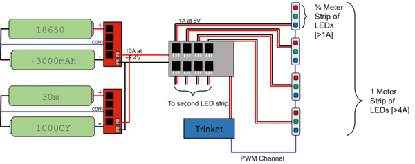
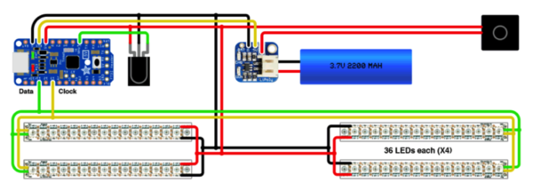
- The power draw of an LED strip is relatively high while on at 100%. We can reduce this amount severely through rapid blinking instead of having the LEDs always on. Theoretically, by employing persistence of vision the LEDs draw a sixth or less than their maximum rated power draw. We only reach a sixth of the power draw when a blank white image is displayed at 100%. This is due to the precision blinking necessary to make an image look the way it does. At most, an LED is given power 60 times per second to create the POV illusion. Based on the time and power supplied to each LED at the time of illumination, the on-time for any given LED is almost exactly 1/6th of a second, and draws 1/6th of it's typical power draw. This easily allows the use a single lithium cell to reach the current draw required alongside a boost converter to bump the battery's 2.7V-3.4V range to 5V. The following is a diagram of this approach.
Final Product[edit | edit source]
The finished design incorporates the following specifications:
- The displaying spokes are two meters in diameter.
- The rotational speed can clearly display content from 300RPM to 1200RPM
- Only two individuals are required to transport the spokes and dolly.
- The device is powered entirely using batteries and can run for ~10 minutes.
- The LED strips' color palette is capable of true color images.
- This machine can be re-created for around $250
- Images are somewhat tricky to upload. They must be flashed with the code.
This product is not quite robust enough for five units, and is more of a proof of concept.
Mechanical Design
The base unit and rotational mechanics are taken directly from design iteration IV. It uses a dolly with hand drill electronics mounted on as a driving motor and power supply. The speed of the motor is driven by a twist knob potentiometer instead of a drill trigger. A cinder block acts as the counterweight for stabilization.
The spokes are constructed of a plastic bowl and aluminum rods. A bolt protruding from its center is used to attach the head-piece into the chuck of the motor on the base unit. All the electronics used to display content are affixed to this piece, and are housed within the bowl.
Electronics Design
The electronics within the bowl are taken mostly from our power concept I. It drives 8 individual strips of LEDs attached to the spokes. Each strip has its own linear voltage regulator and data line and are powered by two lithium ion cells. A Trinket Pro drives the strips and sends out data to each of the eight strips, though this is not a necessary implementation as it was supposed to increase performance, but does not. In order to understand timing and position of the spokes, it uses a hall sensor and magnet mounted outside of the bowl.
Resources and Documentation
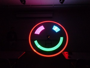
All code used in this project can be found at github. "pov_v5.ino" is the sketch specifically used to display the smiley face found at the top of this page, and uses the 8 individual strip implementation. Version "pov_v6.ino" also incorporates 8-strip methods for a non-pre converted approach, but like the other non-pre converted approaches the Trinket cannot perform the floating point math quickly enough. Every other version is part of a set of iterations of mathematical and logical approaches that attempt to compensate for the Trinket's and LED strips speed limitations. Pay close attention to "pov_v3", as it's a working version that uses pre-converted images. "Pov_v1" is only functional up till about 20 LEDs total.
Safety during operation is important. We have created a video that directs users how to safely operate the Persistence of Vision machine here.
The teams meeting minutes can be found here File:POV 2016 meetingminutes.pdf
The Team[edit | edit source]
| Picture | Bio | Discipline |
|---|---|---|
|
Nathan is a 4th year Senior Mechanical Engineering student at the University of Idaho. He was born in Hillsdale, Michigan, but he was raised in Post Falls, Idaho. He has a beautiful wife and a kid on the way. His hobbies include making pancakes, feeding dolphins, and sleep jogging. |
B.S.M.E. | |
|
Austin is a 4th year Senior Mechanical Engineering student at the University of Idaho. He was born in Seattle, Washington, but he was raised in Post Falls, Idaho. His hobbies include baseball, skiing, computer games, and billiards. |
B.S.M.E. | |
|
Tyler is a 4th year Senior Computer Scientist student at the University of Idaho. He is from Richland, Washington. His hobbies include golf, skiing, and hiking. |
B.S.C.S. | |
|
Zachary is a 4th year Senior Computer Scientist student at the University of Idaho. He was born in Moscow, Idaho, but he was raised in Troy, Idaho. His hobbies include snowboarding, reading, and game development. |
B.S.C.S. |
