Robocodo
| Sponsors |
|
| Team Name | RoboCodo |
| Duration | Fall 2017 - Spring 2018 |
| Advisors | |
| Students |
|
Therapists often spend hours working with patients to loosen the elbow joint manually (through humeroulnar distraction) after surgery to help the elbow recover flexion and extension mobility. There is a need for a device that can do this automatically so that the therapist can be free to work on other parts of the rehabilitation process to decrease rehabilitation time and maximize recovery.
Problem Definition[edit | edit source]
Problem Statement
We are tasked with developing a device that can perform a humeroulnar distraction on the elbow. Ideally, the device will be less than 1 kilogram (kg) and apply a 100 Newton (N) linear force and a 35-40 Newton meter (Nm) torsional force.
Design Goals and Deliverables
- Document which solutions worked and which did not. Explain failures in detail so the company won’t waste time building something that we already tried.
- The gadget should be: comfortable, easy to take on and off, weigh less than 1kg, and have a safety release mechanism.
Specifications
Mobility: Keep arm rigid and allow for adjustment of different angles of pronosupination.
The device should allow for a linear motion which will apply a force just distal to the elbow. It also allows for rotational motion, which will apply a torque to the forearm. Once the forearm is pronated to the correct position, the device should hold the arm rigidly in this position. Misalignment or rotation of the elbow during use of the device could cause injury. The primary opposition to holding the arm rigidly is skin slippage. The motion of the skin allows the underlying bone structure to become misaligned even though the arm is being held tightly. Work to develop a system that will minimize skin slippage.
Strength/Motion: The device should be able to provide a linear force of 100 N and a torsional force of 35–40 Nm. The device will carryout the following motions:
- A force of up to 100 N is placed just distally to the elbow. This is done to release the ulna from the humerus.
- After the ulna is released a torque of 35-40 Nm is applied to rotate the forearm.
- In some cases it is necessary to bring the elbow to its full extension and oscillate back and forth.
Weight: Mass of entire device should not exceed 1 kg on the arm.
The device should ideally be as light as possible. The goal is to maximize patient comfort. To accomplish this, an effort should be made to keep the majority of the weight of the device proximal to the shoulder or back. If the weight must be placed distally on the arm, it should not exceed 1kg.
Safety: Easy to activate quick release.
There is always the possibility that a mechanical device can act in an unexpected way or a patient to react poorly to the procedure. For this reason, the device should have some sort of quick release mechanism, which will immediately release all pressure on the arm. The release mechanism should be easy to activate by both the therapist and the patient.
Feedback: Position feedback for functional electrical stimulation (FES).
In order for the FES system to activate at the right time, the mechanical system must be able to provide some sort of feedback which describes its current position.
Power: Grid power using medical grade power supply
Although the final device is intended to be powered by a lightweight and compact battery pack, it is sufficient for this project to power the device using power supply running off of mains power. If possible, the power supply should be medical grade. All of the wiring should be kept neat and should in no way inhibit the movement of the device or increase risk to the user.
Conceptual Design[edit | edit source]
Overall Look of the Design
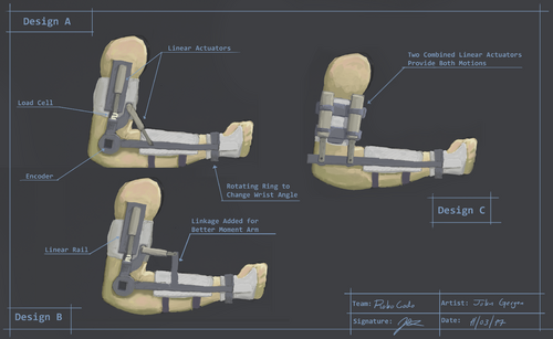
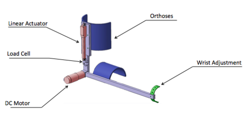
Our goal is to create a prototype similar to the ones illustrated below.
Orthoses[edit | edit source]
Arm and Wrist Orthosis
Use: for attaching the device to the forearm and to hand minimize skin slippage during use.
Materials and Methods for Production: Low temperature thermoplastics can be molded directly onto the forearm and hand which allows for rapid prototyping. They also have adequate rigidity to support the arm while being low cost and easily customizable. We will fabricate an upperarm, forearm, and wrist orthosis from these thermoplastics.
Shoulder Orthosis
| Image | Description |
|---|---|
|
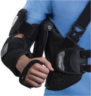
Purpose: Stabilize shoulder and upper arm to help distribute forces to the correct places on the device. Abilities: Allows 30°-150° of adduction and abduction range of motion (ROM). Elbow joint provides full ROM. Adjustments needed: The forearm piece on this device will need to be modified or removed and redesigned to attach to the frame and motors of our device.
|
Frame[edit | edit source]
Layout
| Image | Description |
|---|---|
|
Linear Rail
| |
|
Motor Mount
| |
|
Wrist Adjustment
|
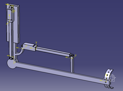
the Frame for the Device
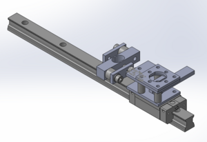
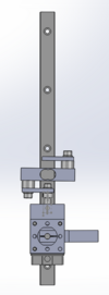
This is our current work in progress SolidWorks model of the frame for the device. Many of the parts in this project are sourced from Mc Master to sacrifice some of our budget for time. The load cell in the model has been adapted into an S-shaped load cell so that we will not need to buy a new load cell.
Electronic Development[edit | edit source]
Micro-Controler
Use: for a feedback system.
Controlled by Button or App: for starters we will test the circuit with the button.
Cost: $200 for all sensors and microcontrollers.
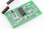
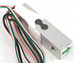
Description: A load cell has been placed in line with the linear actuator so that as well as positional feedback, it will also have force feedback. This was done because the actuator’s built in measurement of position does not give a good estimate of the force being placed on the arm. This load cell was a beam type load cell purchased from sparkfun.com. Spacers and plates were used to transform the load cell from a beam type load cell to an S-type load cell. This cell can take a maximum force of 200 Newtons before it loses its calibration. The load cell uses a HX711 amplifier which is sold as a breakout board on sparkfun.com. The cell is run and calibrated using the HX711 arduino library and the code provide by sparkfun.
| Image | Description |
|---|---|
|
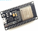
Wireless Communication ESP8266 Chip: Used to communicate with the App to the board ESP8266. | |
|
Load Cell HX711 Micro Load Cell: The sensor we are looking at to measure the fouce of the linear actuators. | |
|
Weight Sensor Amplifier HX711 Amplifier: Used to measure the pressure of the load cell. |
Linear Actuator/DC Gear Motor
We looked into several linear actuators but found that servos weighing under 100g cannot product more than 200N of force. Conversely, actuators that can produce over 200N of weigh between 800 to 1000 grams.
For this project it is more ideal to use lighter weight motors than to compromise our weight goal of under 1kg by using the more powerful actuator.
| Image | Description |
|---|---|
|
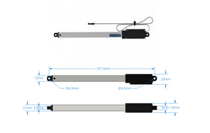
140 mm Stroke 44 lb Thrust Light Duty Linear Servo
|
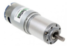
Planetary Gear 12v DC Motor: This is a real workhorse of a motor put into a small package.
This motor allows for high torque while keeping size and weight down.
The actual purchased motor is the Servo City: 12 RPM HD Premium Planetary Gear Motor. Servo City offers the same motor with a rotary encoder installed. Instead of using the encoder version of the motor, which does not give a measurement of absolute position, a potentiometer was placed on the frame which turns with the forearm so that an absolute position measurement can be achieved.
| Image | Description |
|---|---|
|
Planetary Gear 12v DC Motor
|
Electrical Circuit Design
| Image | Description |
|---|---|
|
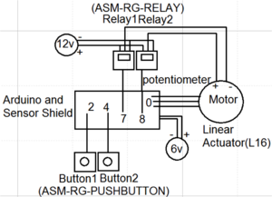
Circuit Design for Linear Actuator This electrical diagram shows how to do basic manual control of a small linear actuator using an Arduino, two buttons and two relays. This linear actuator has a shaft that moves in and out. A potentiometer inside provides positional feedback so that the shaft position can be determined at any given moment. A separate power supply runs to the linear actuator. The DC motor positive and negative wires come from the two relays and then split the positive and negative from the power supply and run two of them into each.
| |
|
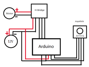
Circuit Design for DC Gear Motor The most basic idea is combine the PWM and the H-Bridge methods to have completely control over the DC motor. Firstly, we can use a PWM signal to control the speed of the DC motor by controlling the voltage to the motor. To control the rotation direction we need to inverse the direction of current flow through the motor by using an H-Bridge. We would like to use a joystick which has two potentiometers to control the motor’s speed and direction.
|
Team Information[edit | edit source]
| Biography | Discipline | ||
|---|---|---|---|
| Genaro Martinez |
Genaro Martinez (aka Henry) grew up in Burley, Idaho. His academic interests include microelectronics and microcontrollers. Outside of school on his free time, he enjoys playing video games, hanging out with friends and drawing. After graduation, he plans on becoming a hard working engineer in the workforce. |
Computer Engineering | |
| Abby Raveling |
I decided to study biological engineering my sophomore year of college when I realized it would give me a unique background for physical therapy. After I graduate, I want to become a pediatric physical therapist and use my engineering background to help develop rehabilitation equipment. My hometown is Hamilton Montana. I enjoy hiking, camping, swing dancing, baking, and rock climbing. |
Biological Engineering | |
| John Gergen |
Senior in mechanical engineering. John has a strong focus on robotics and control systems. For most of his time at the University of Idaho, John has worked on the Autonomous Underwater Vehicles project which gives him a strong background in the mathematics behind robotics as well as strong skills in data analysis and filtering. |
Mechanical Engineering | |
| Jiawei Liu |
Jiawei Liu came from china as a transfer student, and is a senior in electrical engineering. He is super excited to get to learn about new things, and get to know new friends in order to enlarge his social connection; furthermore, he is willing to make friends with people who comes from different countries and to learn about different cultures. His favorite things to do are; sports, outdoors activities, swimming and traveling. Growing up he liked cars and machinery and in hopes to utilize his knowledge in actual cases. |
Electrical Engineering | |
| Meghann Hester |
I am from a town called Woodland, CA. I started mechanical engineering because I enjoyed learning how things worked by taking them apart. I would like to work on prosthetics in the future or some other medical robotics. |
Mechanical Engineering | |
| Jiachen Shen |
My name is Jiachen Shen and I am currently a senior electrical engineer at the University of Idaho. I grew up in Suzhou China. I started my degree in WenZheng College of Soochow University in the fall 2014, and came to UI in the fall 2017 to become a transfer student. I love photography and playing the piano in my free time and they make me enjoy life more. |
Electrical Engineering | |
| Logan Hammons |
I am a senior studying mechanical engineering, I grew up in a small town just outside of Coeur d’Alene ID. Throughout my child hood I learned how much I enjoyed working with my hands to create things, I was always building unique contraptions like catapults or trebuchets. Once I got into high school I gained interest in robotics and mind controlled prosthetics and felt mechanical engineering would give me the best variety of skills to work in that field. I have an entrepreneurial mind set and have a passion for inventing which I hope to use along with my engineering skills to design and develop my own product. |
Mechanical Engineering |
