Solidcam HAAS Mill Startup Guide
Jump to navigation
Jump to search
SOLIDCAM HAAS MILL STARTUP GUIDE[edit | edit source]
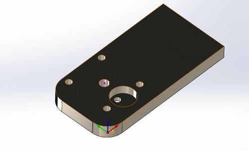
This tutorial details the process of producing a CAM code for the HAAS Mill for using SolidCAM by walking through the process for an example part.
Example Mill Part SolidCAM Tutorial[edit | edit source]
- Open Part in SolidWorks.
- Open the SolidCAM Part Tab in SolidWorks and select New, and Milling.
- In the right side menu select External, create a part name, check the Use Model file directory, box and set you units to Inch
- (Setting Units to Metric will require you to start the process all over).
- In the menu that comes up next, select gMilling_Haas_3x from the drop-down menu. Then under the Define section select Stock.
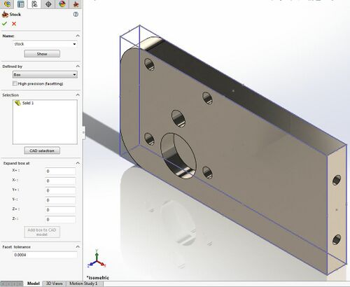
- In the Stock menu, under Defined By make sure that Box is selected. Under Selection click the white space in the box, then select the part. Under Expand Box At set all values equal to zero. This is assuming that your stock is already cut to size. Finally, click the Add Box to CAD Model button to create a box around the edges of the created stock.
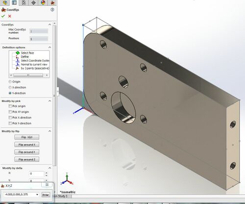
- After clicking the green checkmark, select Coorsys in the Milling Part Data menu. Under the Definition Options select Define. Select a point as the origin, then a point in the x-direction, and a point in the y-direction to create the coordinate system shown. Click the green checkmark on this menu and the next two menus.
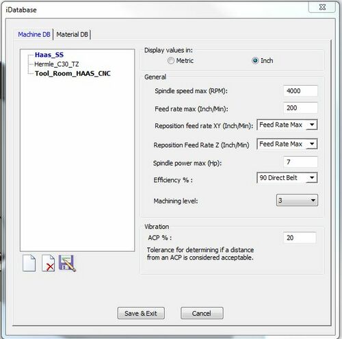
- To input the HAAS CNC Mill that we have in the Machine Shop, click on Edit iMachining Database in the Milling Part Data menu. Select New and then propagate the information according to the image on this page.
- Select Tool_Room_HAAS_CNC, from the tree. Set the material and the machining level* , in the drop-down boxes then click the green checkmark to verify the selections.
- (To be conservative, when machining aluminum, set to the hardest material.)
- * Machining level is the machining aggressiveness level used by the iMachining database to automatically compute feed rates.
- To add the first machining operation go to SolidCAM Operations tab and select the 2.5D drop-down
. In the drop-down menu, select the Profile option.
- Under the Geometry Tab. Select MAC 1(1-Position) in the drop-down and then click on the new button (looks like piece of paper) underneath the CoordSys button.
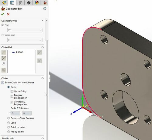
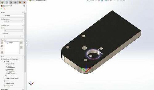
- In the Geometry Edit window select Flat, and in the drop-down make sure that XY is selected. Turn off the Tangent Propagation and Constant Z Propagation check boxes. Hide the box that was added to the model so you can select the two curves and edge connecting them on the side near the origin. Make sure to select them from left to right. The final result is shown in the image below. Click the Green check when complete.
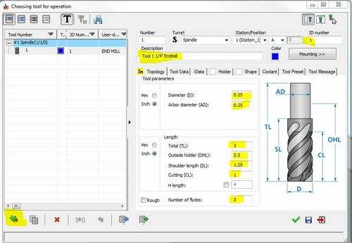
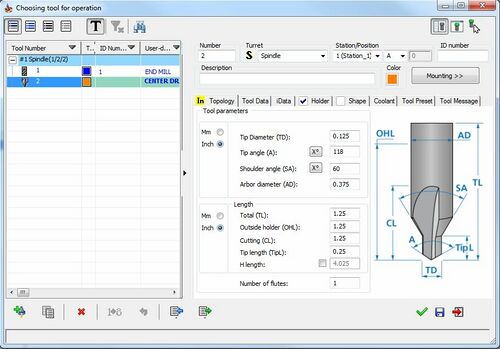
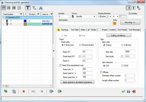
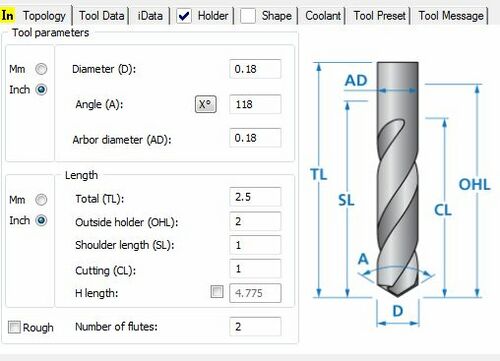
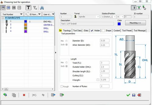
- Under the Tool Tab click select. No tools have yet been created. To create a tool, click the Add Tool button in the bottom left corner. Label the tool and make sure that the dimensions are the same as in the image.
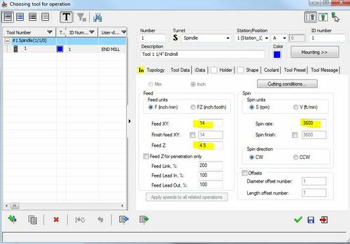
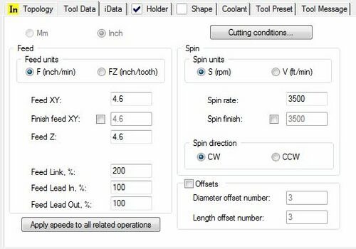
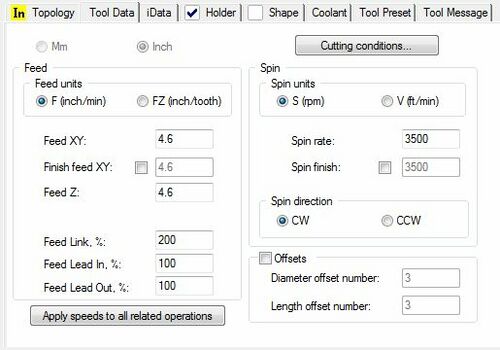
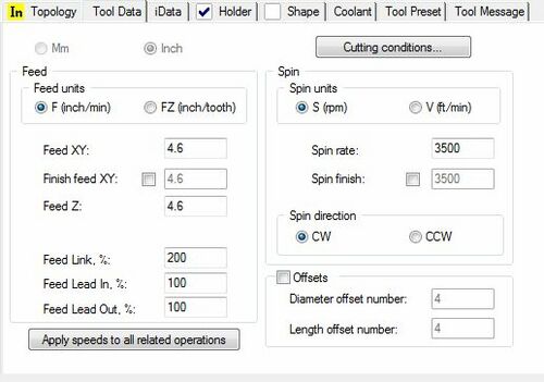
- Under the Tool Data tab, input the numbers that are in the following images and uncheck the necessary check boxes.
- These numbers were calculated from the website in the following link: [1]
- The z-Direction feed should be about 1/3 of the horizontal motion.
- Select an arbitrary holder under the Holder tab, and select Flood: Pressure under the Coolant tab. Then click the green checkmark
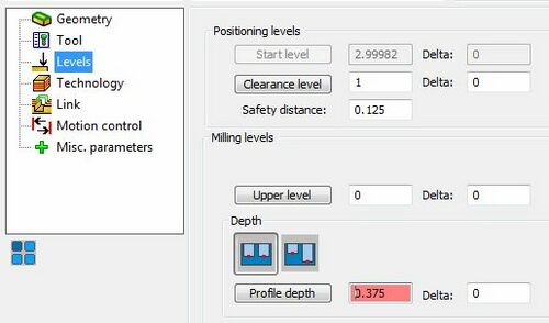
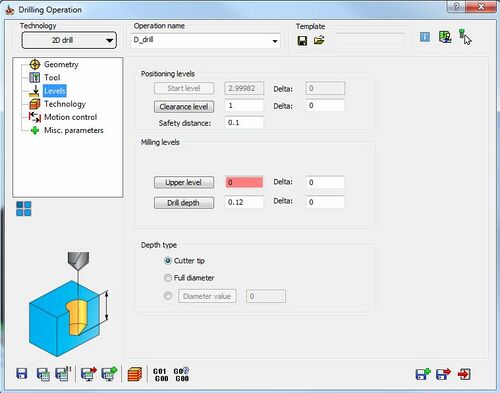
- In the Levels tab Set the Clearance Level* to 1, and the Safety Distance* to 0.125. For the Upper Level set the value to 0. For Profile Depth click on the button and select the bottom face of the part. This should evaluate to 0.375 once back in the Profile Operation window.
- *Clearance Level is the z axis height at which rapid tool positioning occurs and should be high enough to prevent any collisions between the tool and the part or any clamps used to secure the part while the tool is positioned. When the tool is positioned correctly in the x and y direction it will begin to rapidly plunge until it reaches the Safety Distance.
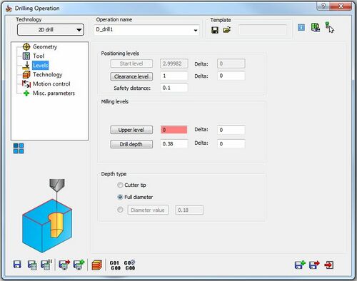
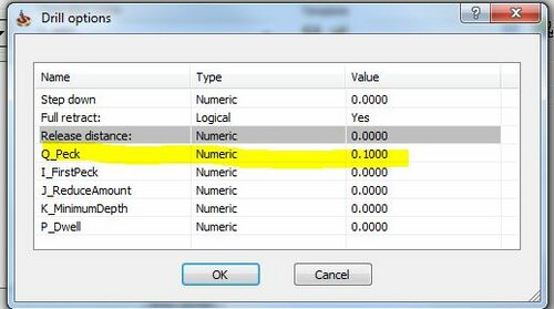
- *Safety Distance is the z axis height at which the tool will begin the machining operation and the position to which it will return in order to clear chips during an operation. This tool plunges slowly from this point. If the operation is a peck drill, Safety Distance should be set high enough that chips can clear the part but not so high that the tool spends excessive time returning to that location.
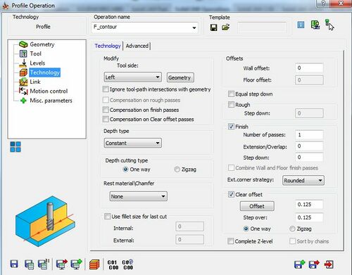
- Under the Technology tab, the rough, finish, step-down and other passes will be set. For the purpose of this part, set these parameters as shown in the image below.
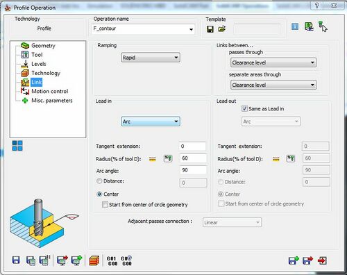
- The Link tab is where the tool control on entry and exit is set. For this part, values are set as shown in the image below. When finished entering parameters, hit the Save and Exit button in the bottom right hand corner.
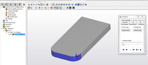
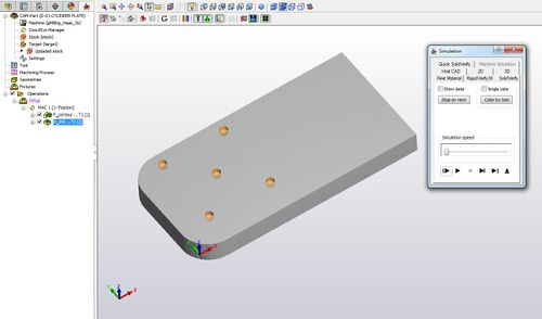
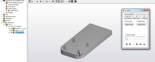
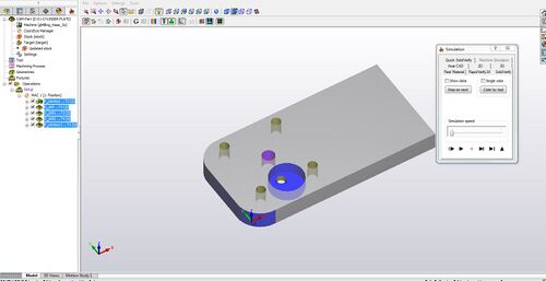
- Under the SolidCAM Operations tab click Calculate All. The toolpath for the F_contour should be generated. If the Updated Stock checkbox is clicked you can verify that the material was removed correctly. If you right click on the operation and select Simulation and Solid Verify. You can watch an animation of the toolpath just created. The result should look like the image below.
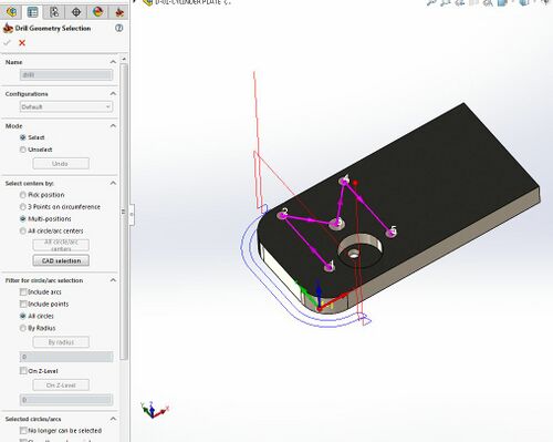
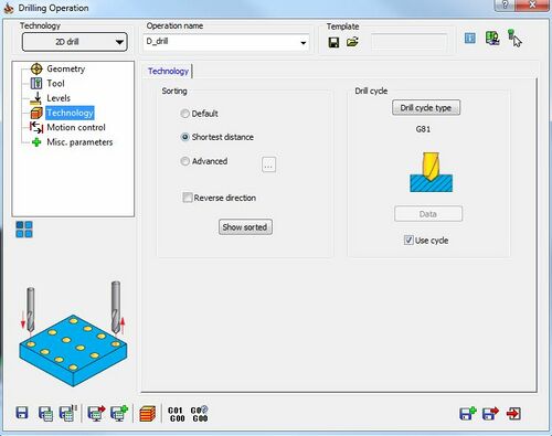
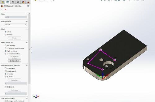
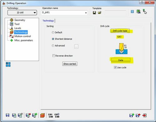
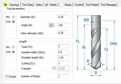
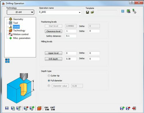
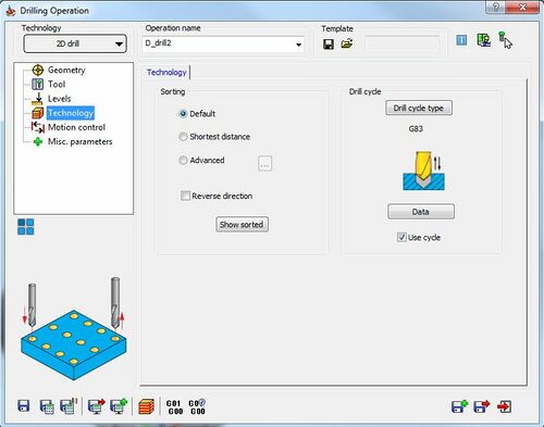
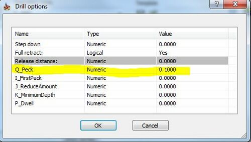
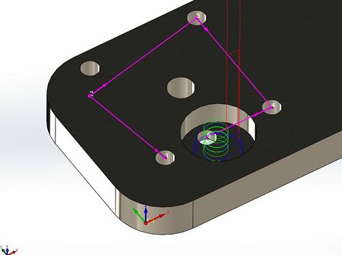
- The next feature to be created is the holes. These can be created in a similar fashion. Select the Drilling Operation from the 2.5D menu. The settings used for this tutorial are shown in the following images.
- Repeat for the 0.18 inch hole.
- Repeat for the tapped hole.
- Finally we will create the Mill Path. Select Pocket under 2.5D.
- Select the large hole.
- Select tool number 1. There is no need to change settings.
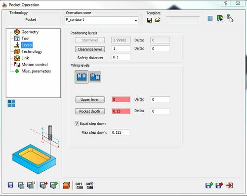
- Change the Clearance Level, and Safety Distance. The upper level should be the top surface and the pocket depth should be the bottom of the hole. Check Equal Step Down and set Max Step Down to 0.125.
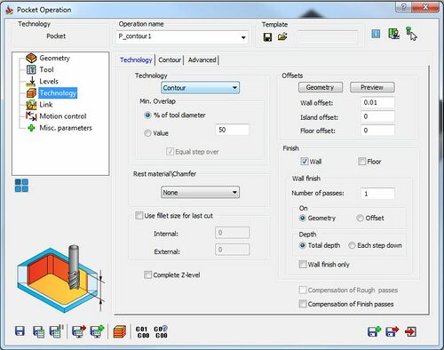
- Set finishing instructions and pocket type.
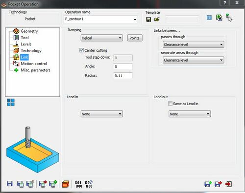
- Set to vertical entry
- Add bottom hole to other operations
- Center Drill Operation:
- 0.18 Drill Operation:
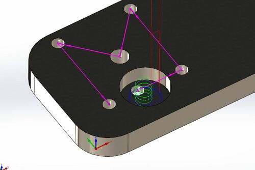
- Preview the final simulation:
- Select the large hole.

