Tramming Mill Head
This article goes through the process of tramming a mill head.
Tramming is the process of ensuring that the mill head is perpendicular to the mill table in both the x and y axis. The benefits of having a properly trammed mill head are:
• Ensures that milled surfaces are mutually perpendicular.
• Prevents a saw tooth patter from forming on milled surfaces.
• Ensures that tools are perpendicular to the mill table.
Tools For Tramming
| Tool | Description |
|---|---|
| The dial indicator will be attached to the mill chuck and be used to determine changes in orientation of the mill head.
The mill wrench will be used to loosen the various bolts on the mill head and also to turn the adjustment bolts of the mill head. |
Tramming Process
| Step | Description |
|---|---|
| To setup the mill for tramming, move the vice out from under the mill head and remove the protective plate on the side being utilized for the tramming (either the left or the right).
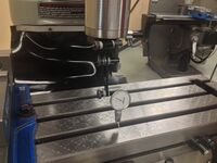
The dial indicator can now be attached to the mill head chuck. The dial indicator should be angled outward and down from the mill head. Once in place, raise the mill table so that there is contact with the indicator and that the indicator has anywhere from 0.005 to 0.010 inch preload (from no load to 0.005 – 0.010” of travel on the indicator). |
The x-axis is defined as the feeding direction of the mill bench (left and right when facing the front of the mill). See: Mill Axis
| Step | Description |
|---|---|
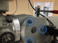
| To begin tramming about the x-axis, there are six bolts, three on each side of the mill, that need to be loosened using the mill wrench or other fitting wrench. The bolts should be loosed and then tightened to just beyond hand-tight (about ¼ turn past hand-tight with the appropriate wrench). | |
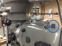
| The adjustment bolt to move the mill head up and down about the x-axis is located near the feed handle for the mill head. By twisting this bolt clockwise and counter-clockwise the mill head will move accordingly.
Located adjacent to the adjustment bolt are two protractors. The large vertical one (the smaller red arrow on its own template will be used for adjustment about the y-axis) located on the mill head has a red indicating arrow which should be aligned with the zero marker on the curved protractor located on the body of the mill. These protractors provide a general guide to alignment, however, the dial indicator will be necessary to perform the final adjustments. | |
| With the dial indicator positioned at the front of the table (with the 0.005 to 0.010 inch preload), zero the dial indicator by twisting the outside cap to align the zero with the dial. It is important to measure on a no damaged surface of mill table (the table may need to be shifted in order avoid gaps on the table).
With the dial zeroed and the spindle in neutral position, rotate the chuck (apply force to the dial’s clamp that is attached to the mill chuck to avoid altering the dial’s vertical configuration) so that the dial indicator is now on the back end of the table, ideally a 180 degree turn. Noting the direction that the dial rotates (a clockwise reading requires that the mill head be moved up, while a counter-clockwise reading requires that the mill head be moved downward), determine the direction that the mill head needs to travel. | |
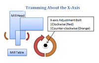
| The diagram provided shows how movement of the adjustment bolt correlates to movement in the mill head. Once confident in the correct actuation direction of the adjustment bolt, adjust the mill head so that ½ the difference between the front and back measurement is reached. For example, if the front reading is zeroed and the back reading is 0.010 inches, adjust the mill head so that the dial reads 0.005 inches closer to the zeroed reading.
After the first adjustment is complete, choose a side to zero off of. This can either be the front side or the back side. It is recommended to zero off the same position to avoid confusion, however, it is not necessary. Continue the adjustment until a difference in reading between the front and the rear is no greater than 0.002 inches. Once satisfied with the readings, begin re-tightening the bolts that were loosened, tightening them evenly in rotation to prevent change in the tram. Recheck the measurement between the front and the rear to ensure that the mill head did not adjust significantly from tightening. |
| Step | Description |
|---|---|
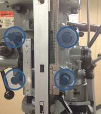
| To begin tramming about the y-axis, there are four bolts on the front of the mill that need to be loosened using the mill wrench or other fitting wrench. The bolts should be loosed and then tightened to just beyond hand-tight (about ¼ turn past hand-tight with the appropriate wrench). | |
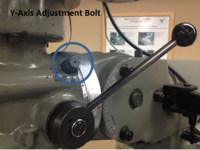
| The adjustment bolt to move the mill head left and right about the y-axis is located at the top-rear of the mill body. By twisting this bolt clockwise and counter-clockwise the mill head will move accordingly.
The indicating arrow on the protractors for tramming around the y-axis is located on a standalone plate that is in contact with the vertical protractor. This indicating arrow and the zero on the vertical protractor can be used to estimate a starting point for tramming. | |
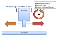
| The diagram provided gives information on how the adjustment bolt for tramming about the y-axis affects the mill head. Use the same process as described for tramming about the x-axis, however, use locations left and right of the mill head as your reference points in contrast to the front and the rear as done previously.
Once the adjustments are complete, tighten the bolts on the head of the mill and check measurements about the x-axis and the y-axis. It is possible that the tram in either direction can be altered from tramming the other and the re-tightening of the bolts. Ensure that all measurement are within 0.002 inches. If the measurements are not within tolerance, the tramming process will have to be reworked. |


