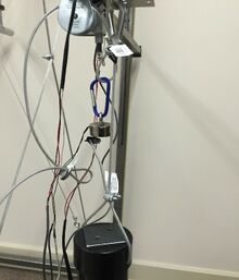
Trunk Bending Apparatus
| 2016 Capstone Senior Design Project - University of Idaho | |
|---|---|
| Team Name | TWISTERS |
| Sponsor | Rajal Cohen, Ph.D. - Department of Psychology and Communication Studies |
| Faculty Advisor | Michael Maughan, Ph.D. - Department of Mechanical Engineering |
| Technical Liason | Brian Hanson - Department of Mechanical Engineering |
| Donor | Dr. Victor Garfinkel - Oregon Health and Science University |
| Team Members | Hai Yu, Husain Altaqi, Jennifer Downen, Tristan Higgins |
| Duration | Summer 2016 - Fall 2016 |
Trunk stiffness and stability can be related to the posture and alignment of the human body. This project continues on the evolution of the Twister, a Trunk Stiffness Bending Device, that is intended to measure and acquire data of axial and torsional stiffness in core muscles. Then, postural performance can be used to measure torso stiffness in order to examine muscle reaction patterns with the consideration of age, height, weight, and other factors.
Background
In the 1980's, Dr. Victor Gurfinkel, medical researcher at Oregon Health & Science University, developed the Twister to measure torsional muscle tone as well as muscular responses as the apparatus twisted the subject. The body sections considered by the Twister are the neck, trunk, and waist. Then, Dr. Gurfinkel devoted the apparatus to Dr. Rajal Cohen at University of Idaho, Psychology & Communication Studies Department, upon his retirement.
The developers of the Twister seek to study the psychological mechanism caused by the change in length of muscles crossing a selected region as a result of the device twisting that region. The resulting resistive torque is determined to calibrate the tonic control of all muscles subjected to changes in length. Based on peek-to-peek magnitude, phase of resistive torque, and tonic electromyogram modulation, the results being acquired show magnitude and dynamic control of muscle activity. Moreover, Fay Horak, another developer of the Twister at Oregon Health & Science University, believes that the Twister will help answering how the brain controls normal postural tone, and how abnormal tone can be improved with treatment [[1]].
Problem Definition
The previous team assembled and modified the structure of the device to be relevant for the trunk bending experiments. They created an interface software to collect data, upgraded the hardware, and built harnesses. The objective is to bring the machine into an operational state by using higher quality parts, completing circuitry, improving codes and the interface, making the machine more user-friendly, adding safety features, and testing, collecting, and researching data from the final product.
Initial Project State & Goals
Proceeding the project from the point reached by the previous team:
- New string potentiometers are needed to withstand the weight applied and be durable. As new potentiometers are going to be used, the circuitry to the power supply and computer needs to be set up differently and the software interface created last year needs to be reprogrammed.
- New timing belt and pulleys are to be replaced for the bottom potentiometer.
- The wiring of power supply seems to be done incorrectly therefore, the power supply has to be rewired correctly to the computer and all sensors.
- The current neck bar has only one universal joint and as a result, the subjects neck has to bend along with the movement of the neck bar. To allow movement while the subject's neck is still perpendicular to the ground, two universal joints are to be installed so that one cancels the bending angle of the other.
- Torque sensors need to be reconnected correctly to the power supply then, they need to be tested to analyze the data they acquire.
- The current attachment bar system is not practical and can hardly be placed accurately. Therefore, a roller system is going to be added to the lateral bars so that the bars remain horizontal and can be slid up and down easily.
- The DC motor has to be connected to the circuit. The code controlling the motor has to be revised to work with the changes made to the drive system as the timing-belt and pulley there are going to be replaced with new ones.
- The code and interface need to be completed and improved to function as demanded.
- An emergency stop is to be added to the system for safety at a proper location that can be easily reached by the user.
- The design of the second lateral bar attachment, which holds the user stationary, needs to be improved to be adjustable and durable.
- The flat spring that connects to harness holders break faster than expected therefore, a new design has to be developed to be durable while still allowing natural movement.
- The current system does not have a physical safety stop when the platform rotates. Therefore, a physical stop is to be added to the system to have the turntable stops at a certain degree while still achieving maximum rotation required.
Design Specifications
| Specification | Specific Requirements | Target Value |
|---|---|---|
| Frame Height | Twister frame must fit in the Mind and Movement Laboratory | Frame must be 8 feet or shorter |
| User Height | Accommodate user heights of 5-95 percentiles | Minimum requirement for maximum height must be 6'1" |
| Lateral Force Perturbation | Apply a lateral force between 5-10% of subject's body weight | Maximum of 30 lb (for a 300 lb person) |
| Ease of Assembly | Assembly/Disassembly requires minimum amount of people and time | 1-2 people, 20 minutes or less |
| Mobility | Minimize the amount of force required to move the Twister | Have a SUS score of 68 or above |
| User Interface | Simple GUI for user | Have a SUS score of 68 or above |
| Twister Usability | Overall usability | Have a SUS score of 68 or above |
| Motor | Motor speed variability | Must be capable of running between 0° and 4° per second |
| Emergency Stop | Motor stops rotating when E-stop pressed and turntable is free be adjusted; not locked | <= 0.5 second response |
| Point of Max. Rotation | A point of rotation that turntable stops at | up to 20° to the left or right; total of 40° |
| Universal Joints | Should have a minimum amount of slip in them to get accurate data | <= 0.5 degrees if slip |
| String Potentiometer | Its string has to have a certain length so that it does not limit the travel of the weights when dropped | > 10 inches |
| Power Supply | Powers string potentiometer and torque sensors | 5 V |
| Torque Sensor | Obtain Torsional data during twisting | Non-linearity of +/- 0.2% of rated output |
Mechanical Twister
Turntable
The previous gear ratio on the DC motor system at turntable was 1:1 while the gear ratio had to be higher. Two options were available for the team to choose from. Whether to get a new potentiometer or to get a new timing-belt and pulley to increase gear ratio. However, there were limited options of pulley sizes available for sale that would get the system to reach the ideal gear ratio. Therefore, the team settled for a 1:6 gear ratio based on the available timing-belts and pulleys for sale. As to avoid coding errors, changing the current code, which was working fine, and since the belt used there did not have teeth, the team decided to get a new timing-belt to prevent slip in addition to a new timing pulley. The team have seen the pulleys the previous team have made, and found that they’re too sticky and could easily break therefore, it was decided to get a new timing-pulley for the new belt to meet accuracy and get a durable material.
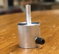
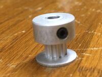
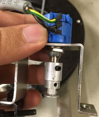
Now, the potentiometer pin will not fit into the new pulley since the pulley is small in size. Also, the belt will not be parallel with the plate below it and that may affect its function. Therefore, a potentiometer plug extension, which extends the potentiometer to connect and to rotate along with the pulley, has been machined. A belt tensioner is added to the potentiometer to keep the timing-belt in tension. The belt tensioner works by attaching it to the holder of the potentiometer then, the bolt of the tensioner is tightened to to pull the belt towards the tensioner which is in opposite direction the the timing pulley. As a result, the potentiometer stays in tension.
| Items | Description |
|---|---|
| The potentiometer extension that plugs into the pulley below it and has the potentiometer pin plugged into it and they all rotate together. | |
| The pulley that the potentiometer extension is plugged into. This part brings motion to the potentiometer. | |
|
The previous two parts assembled with the potentiometer. When the DC motor is on, it moves the timing belt which moves the small pulley attached to the potentiometer and at the same time, the potentiometer rotates along with them. |
Emergency Stop
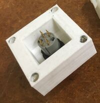
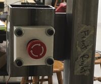
A plate and a rectangular bar has been welded together to make the stand for the emergency stop. In addition, a box to hold the emergency stop has been 3D printed.
| Items | Description |
|---|---|
|
The white box is the emergency stop box that has been 3D pritned, and the emergency stop is attached to it. | |
|
This part is the stand that holds the emergency stop. The thin plate is bolted onto the right front vertical bar of the Twister. The right side is chosen as right-handed people are the dominant group. Then, the emergency stop box is bolted onto the rectangular section of the stand and has the wires coming out from the open section to connect to the power supply. | |
|
This is the final position of the emergency stop in place. |
T-Plate Harness Attachment
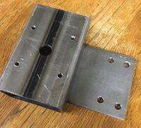
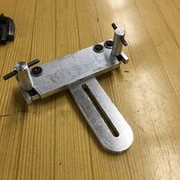
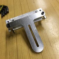
A T-plate that attaches to the harnesses is missing therefore, a new one has been machined at the machine shop, shown below.
 |
|
Second Lateral Bar Attachment
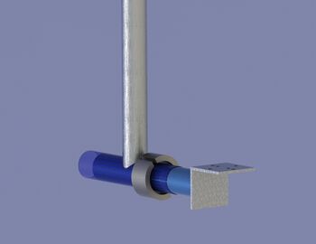
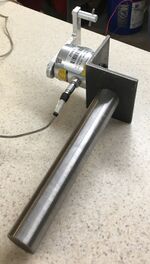
The second lateral bar attachment is behind the main lateral bar. It allows the user to restrain the hips or attach a torque sensor to it. The sensor allows one more area to analyze on the person. The design of the lateral bar includes a vertical bar that can be moved up and down as well as a horizontal bar that moves closer and further away from the test subject. This allows more adjustability depending on the height and size of the person. There is also a thin piece of metal that allows a person to move naturally in the y-axis. This metal consistently breaks without the adjustability because it bends too much. The added adjustability fixed this problem. The torque sensor and the harness are attached using an angle iron welded to the horizontal bar. The angle iron can attach to the torque sensor which will attach to the harness attachment. Also, the angle iron can directly attach to the harness attachment.
 |
|
Bending Bars
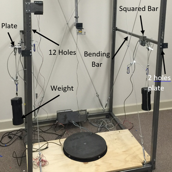
The bending bars are the two bars attached to the frame on the left and right sides. Each bar consists of the bar itself and two plates, one welded to each end of the bar. The plates have two holes in them where given bolts can slide through. Now, there are 4 vertical frame bars, each have 12 through holes drilled to allow height adjustment of the bending bars. The height desired is chosen then, bolts are put through the bending bar plates to go through the frame. After that, nuts can be used to lock the bending bars in place. The advantages of this design is the stability of the bars withstanding a variety of weights without sliding in the vertical direction or shaking noticeably as they’re locked by the bolts and nuts. Moreover, this design assures the bars are horizontal while the previous used clamps on each end of the bar which may cause a slope.
|
Stability & Turnbuckles
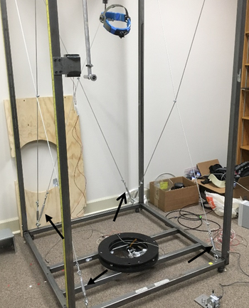
The frame was unstable and used to wiggle noticeably when pushed or an action was taken onto the frame. That was a potential issue as it might cause problems when the weights were to be dropped for the bending mode as it might affect the results or damage the system. Therefore, the team thought about welding triangles at the edges of the frame. However, the issue was that we would not be able to fit the apparatus in the welding area at the shop. Also, if we take the apparatus apart we wouldn’t be able to weld every edge. Next, Tristan thought about using adjustable straps to be attached from one top corner to another bottom corner on the opposite side of the first corner. The straps improved the stability of the frame however, they were not practical for the longer term. That led to another solution which was using turnbuckles to be attached the same way as the straps. After that, the team ordered 6 turnbuckles, 2 for the rear, 2 for the right side, and 2 for the left side. The turnbuckles were successful in improving the stability of the frame and it became more rigid and stable. Below is a picture of the turnbuckles installed.
|
Neck Bar
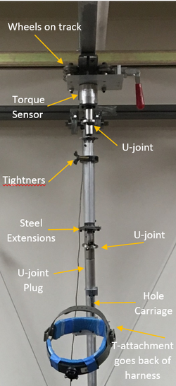
The neck bar is the complete assembly starting from the top of the frame down to the harness attachment. The neck bar is attached to a plate with wheels to slide on a railroad attached to the top frame.The assembly has two universal joints for the subject to be able to move his/her head in all directions without being restrained while the previous design had only one U-joint which restricted the subject's movement forcing the him/her to bend their neck diagonally when moving along with the U-joint. Also, the neck bar includes an adjustable bar to adjust the height of where the head harness is desired to be considering different heights of subjects allowing for heights from 5'5" to 6'2".
|
Electrical Twister
Wiring/Connections
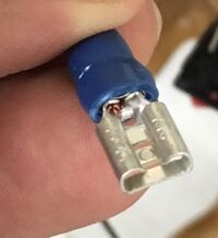
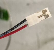
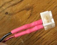
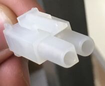
To understand the circuitry of the apparatus and to know where and how to connect additional devices, all of the circuits have been disconnected then, have been rewired from scratch and that helped the team modify the wiring as needed for making the Twister more user-friendly specially, for the ease of movement of the whole apparatus from one location to another. Moreover, a different set of electrical connectors and plugs have been used to be able to disconnect/unplug most of the wires easily when the Twisters needs to be disassembled for moving it. Moreover, reconnecting/replugging the wires the wrong way has been prevented by using male and female plugs. The blue single wire plugs plug into each other, the two wire plugs with white heads plug into each other, while the emergency stop plug is of a bigger size than the previous ones therefore, they cannot be mistaken.
| Male Plugs | Female Plugs |
|---|---|
String Potentiometers
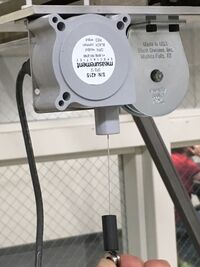
Instead of the 3D printed string potentiometers, two 10k Ohms string potentiometers have been ordered and installed on the lateral bar attachments for the sake of durability and the accuracy of measurements being acquired. The string potentiometers are connected to the 5V power supply as well as a BNC cable that goes to the computer. The potentiometers have been tested using an Oscilloscope and it displayed accurate measurements of displacement.
|
Copper Board
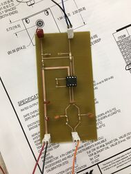
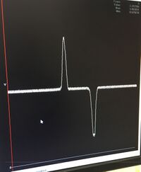
A board has been added to the apparatus to filter out the noise resulting from the torque sensors as well as to increase the gain in the signal acquired. The torque sensors had so much noise that the signal could not be read clearly therefore, a copper board has been developed to reduce the noise. An ADD622 operational amplifier has been added to the copper board then, the layout of the board was based on it. As a result, the torque sensor signal is now readable. Moreover, the center of the signal fluctuates around 2.3 V and by deflecting the torque sensor a minimum of 0.623 V and a maximum of 3.86 V has been acquired as shown below.
| Copper Board | Signal Acquired |
|---|---|
Electromagnets & Relay
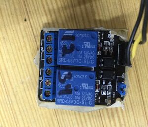
The electromagnets hang two weight houses to provide axial force in bending. Two electromagnets hang on each plate of the Twister. They're hooked up by pothooks and attached to the cables that go to the harness. A solid state relay is used between electromagnets and Arduino Mega. This relay switches capacity available by 10A in spite of small size design for high density PC board mounting technique. The relay will allow current to flow or shut it off from the magnets, turning the electromagnets on or off, respectively.
Overall Achievements/Improvements
The team successfully brought and upgraded the following:
- Installing new U-joint with zero backlash.
- Shortening the neck bar to allow from 5'5" to 6'2".
- Improve the design of the 2nd torque sensor attachment.
- Machine new T-attachment for the 2nd torque sensor attachment.
- Improve code and interface to work successfully and to be more user-friendly for future use.
- Get the motor to successfully run and installing new ribbon connector to be attached to by the motor.
- Increase precision and accuracy by purchasing new a timing-belt and a timing pulley.
- Develop new bending bars with higher stability and accuracy.
- Build a mechanical safety stop for maximum rotation.
- Install an electrical emergency stop.
- Get a new 24 V power supply to power the drive system.
- Get a new 5 V power supply to power the torque sensors and string potentiometers.
- Eliminate noise in torque sensor signals and increase the signal gain.
- Move the Twister to Dr.Cohen's lab.
- Test torque sensors & string potentiometers with Dr.Cohen's computer using MotionMonitor on her computer.
Team Members
| Picture | Bio | Discipline |
|---|---|---|
| Hai Yu:
I’m Hai Yu. I come from northeast of China. I’m a transfer student and I studied in Northwest A&F University in China for two years. Both my major in China and here is mechanical engineering. I'm interest in cars. I like reading and playing basketball. I plan to graduate in the fall of 2016. |
Mechanical Engineering | |
| Husain Altaqi:
I'm from Kuwait, I've been in the U.S since 2010. I'm graduating on Spring 2016. I'm very fond of cars and seeking to know more about engines to modify and tune them. I play the piano, the guitar, and I like designing programs such as Photoshop and SolidWorks. |
Mechanical Engineering | |
| Jennifer Downen:
My name is Jennifer Downen, and I am from Emmett, Idaho. I am majoring in Mechanical Engineering and I have a job at Puget Sound Naval Shipyard. I am going to Thailand for 12 weeks after I graduate! |
Mechanical Engineering | |
| Tristan Higgins:
I am a senior studying mechanical engineering. I would like to use my degree to go into manufacturing and design the machines as well as the processes that are used to make products. Aside of mechanical engineering my interests are outdoor activities such as hiking, fishing and camping. My favorite trips are ones where I get far out into the wilderness for a couple of days or more. |
Mechanical Engineering |
Document Archive
- Meeting Minutes
|
File:TWISTERS Summer2016 Meeting Minutes.pdf |
- Other Project Documents
|
File:TWISTERS Team Contract.pdf |


