Trunk Stiffness Bending Device
| 2015-2016 Capstone Senior Design Project - University of Idaho | |
|---|---|
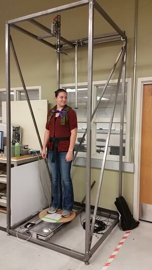
| Original Twister mechanism before modifications and additions | |
| Team Name | P3 |
| Sponsor | Rajal Cohen, Ph.D. - Department of Psychology and Communication Studies |
| Faculty Advisor | Joel Perry, Ph.D. - Department of Mechanical Engineering |
| Technical Liason | Eric Wolbrecht, Ph.D. - Department of Mechanical Engineering |
| Donor | Dr. Victor Garfinkel - Oregon Health and Science University |
| Team Members | Sally Mei, Jacquelin Remaley, Austin Steiner, Robert Regent |
| Duration | Fall 2015 - Spring 2016 |
Trunk control and postural habits greatly influence muscle movement in the rest of the body. This project encompasses continued development of a device designed to measure axial and torsional stiffness in the core muscles of the human body. Gathered data will be used to associate muscle reaction patterns with changes in mobility due to age, height, weight, neurological disease and other psycho-physical factors.
Problem Definition[edit | edit source]
Our goal is to upgrade the Twister's mechanical and electrical components and determine how to make the device functional in an Motion Capture Laboratory. A subsystem consisting of a mechanism to detect lateral responses caused by external forces will be added to the existing structure to allow for a more complex data analysis of human axial tone.
Background[edit | edit source]
Dr. Victor Gurfinkel and Paul Cordo developed the Twister device while at the Department of Neurology at Oregon Health and Science University. It was then donated to Rajal Cohen at the University of Idaho. The Twister measures torsional resistance and muscular responses in standing subjects during the twisting of the body axis. The device can be flexibly configured to study various aspects of tonic control across the neck, trunk, and/or hips. [[1]]
Studies have shown that a person's state of mind can influence how they act, move, and react to known and unknown lateral forces. Hunched and arched posture can influence other muscles in the body and can increase the chance of injury. A person with relaxed mood will typically have a relaxed posture, just as a person with a high stress levels will usually have a rigid posture.
Researchers would like to compare data relating mental to physical responsiveness to determine the cause and effect of negative postural habits. These habits can affect the outcome of a bad fall for an elderly person. The leading accidental causes of death for people aged 60 and above are falls; senior citizens that do survive a fall have a 90% chance of a fracture of the hip. The Twister can evaluate their current posture to determine their likelihood of sustaining injury.
Design Specifications[edit | edit source]
| Specification | Specific Requirements | Target Value |
|---|---|---|
| Frame Height | Twister frame must fit in the Mind and Movement Laboratory | Frame must be 8 feet or shorter |
| User Height | Accommodate user heights of 5-95 percentiles | Minimum requirement for maximum height must be 6'1" |
| Lateral Force Perturbation | Apply a lateral force between 5-10% of subject's body weight | Maximum of 30 lb (for a 300 lb person) |
| Ease of Assembly | Assembly/Disassembly requires minimum amount of people and time | 1-2 people, 20 minutes or less |
| Mobility | Minimize the amount of force required to move the Twister | Have a SUS score of 68 or above |
| User Interface | Simple GUI for user | Have a SUS score of 68 or above |
| Twister Usability | Overall usability | Have a SUS score of 68 or above |
| Motor | Motor speed variability | Must be capable of running between 0° and 4° per second |
Reassembly[edit | edit source]
The Twister device arrived completely disassembled and without a definitive guide of how to reassemble it. In the long run, this was very beneficial. The team had to quickly learn how the main mechanism worked, how data was being collected from the torque sensors, and how the data was sent to the data acquisition software. Simultaneously, assembling the Twister gave insight into the details of the project requirements. For example, there were a few components not included in the Twister parts package, so a redesign for these components was required.
The headpiece originally attached to the frame via a thick piece of foam to restrict the subject from full rotational motion. A replacement design consists of a universal joint connected to a telescoping tube. This will retain the original design intent while making the component more efficient and easier to replace.
The original Twister collected data from torque sensors and translated it into usable data for the Data Acquisition System (DAQ). A computer with Spike Data Analysis software as well as a program to control the DC motors on the Twister turntable was included in the package. After assembling the hardware, we ran and tested both pieces of software with the Twister. When launching both programs for a complete test, a "Missing 1401 Driver" error occurred. This error led to the discovery that the DAQ was not included in the package, and needed to be replaced.
Design - Alternatives and Selection[edit | edit source]
The main challenge in upgrading the Twister was overcoming the age of the system. The original components, created in 1999-2000, were simply not compatible with the client's technology, so much of the electrical system and software was included in the design phase of the project.
Software for the User Interface[edit | edit source]
The Twister application originally operated through a Guided User Interface (GUI), which sent instructions to the circuits that ran the DC motor what procedure, length, and speed to operate at. Data outputted by the torque sensors was converted and sent to a data acquisition box, the CED 1401, and interpreted by data acquisition software a software program named Spike. The CED 1401 DAQ was not included with the system. A newer model was available, but at $5500, it exceeded the budget. To use the same computer tower, a DAQ tool that was compatible with Windows 2000 .NET framework would be required; however, such a device could not be located. Therefore, the decision was made to redesign the user interface, as well as the data acquisition method.
The Twister software was a C# Windows Form Application made using Visual Studio 1999. That version of Visual Studio used a different .NET framework than the current model, so a direct conversion of the software was not possible. Using C# allowed the current version to be compared directly to the original for requirements and procedures.
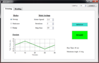
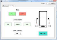
The GUI needed to provide the user with the same options as in the original in addition to selections for the new lateral motion attachment. It will have two main sections, "Twister Control" and "Lateral Movement." The Twister Control section will be very similar to the original. There will be three selections for type of movement; ramp, staircase, and sweep. Inside these selections, the user can edit the motor speed, turn iteration, turn duration, and a delay, if applicable. The Lateral Movement section will contain the control for the electromagnets that are the heart of the lateral movement design. The user can select 'Right,' 'Left,' or 'Random,' and when they run the program, the electromagnet will switch off, dropping the corresponding weight and pulling the subject.
Adding the Lateral Attachment to Twister meant that hardware needed to be added to the existing components, and modifications needed to be made to the existing code. Because the CED 1401 Data Acquisition System was not included with Twister upon deliver, and an exact replacement could not be found, a new data acquisition system was needed. The best solution we found was creating our own DAQ and modifying the electronics to fit around our system. Options for a new interface included a MatLab generated user interface and a Visual Studio interface. Basic interfaces to control an LED through an Arduino were created on each platform, and after much discussion, Visual Studio was chosen to create the new Twister interface.
Data Acquisition System and Electrical Hardware[edit | edit source]
A need for a new data acquistion system came early in the project, as the original DAQ, CED 1401, was not included. A secondary requirement from the client was that Twister could be connected to the Motion Monitor Camera system, so that sensory data could be compared side-by-side with visual data from Motion Monitor. The Motion Monitor System included an analog to digital converter, and to keep within budget and simplify the system, was used as the data acquisition system for the sensory data outputted by Twister. Another decision was made early to replace the existing electronic components with more up to date components. The original system composed of six 8-bit microncontrollers acting as slaves to a 16-bit master controller, along with many other individual op-amps and circuits. We found it easier to replace the system than add to it.
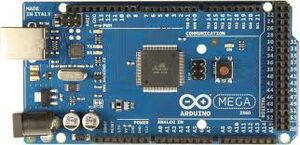
The Twister needed a replacement for its main electrical controller. A decision was made fairly early on to use an Arduino Mega 2560. It has numerous connections, an impressive processor, and has an incredible amount of support through its website and other Arduino users. The torque sensors, Futek TFF400, came with the original equipment, and after testing, we found to be useful to the project. They send data via a LEMO connection, so a circuit was designed to convert the LEMO output to the BNC connection that Motion Monitor uses.
Detailed Design - Hardware[edit | edit source]
The following sections outline more details of the Twister's hardware.
Pulley System[edit | edit source]
A pulley system is used to create a lateral force on the test subject. The system is composed of two pulleys on the left and right sides of the Twister frame. A cable attached to the electromagnet runs on top of the pulley and attaches to the subject standing inside the Twister frame. To cause a lateral perturbation, voltage is cut off from the electromagnet and the magnet releases the weight. The weights are only released from one side of the Twister at a time. To cause a reaction to the left side of the user, the weights are released from the right side of the subject. Steel bars in various sizes are used for the weights in the pulley system. Voltage control is provided by the microcontroller and triggered by the user interface.
The design that Twister is being based off of calls for a weight drop of 7% of total body weight. The example design exposed test subjects to forward and backward forces on their torso, as oppose to side to side forces with the Twister design. For this reason, varied weights are included so the client can choose the desired force on a case by case basis, with a maximum weight of 15 lbs. The maximum weight was decreased for the Twister model in comparison to the example model out of concern for lower back injuries from sudden side-to-side jolts in the test subject. A 24 Volt electromagnet was chosen for the pulley system so it could be powered without any additional circuitry from the 24 Volt power supply used for the rest of the system. The electromagnets are triggered by the user through the microcontroller, the Arduino Mega 2560. A solid state relay was used as an electrical switch between the voltage supply and signal.
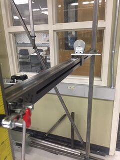
The Attachment bar is one of the main parts of the lateral force test on the Twister. The Attachment bar serves as the adjustable bar that shelves the pulley and BNC housing; it also provides the support needed for the weights to be hanging off the pulleys. The bar needs to be able to support a minimum of 20 [lbs]. Calculations have been done to calculate the amount of force the bar can hold, which is approximately 50 [lbs], with a safety factor of 3. The design requirements for this bar was that it needs to be able to support a minimum weight of 20 [lbs], it to be easily adjustable, and compact. The assembly has four different parts, the clamp, the bar, the bracket, and the rubber strip. The clamp and rubber strip was purchased form McMaster-Carr. The bar is a piece of 1”x1” steel tube with ¼” walls and the bracket is a piece of ¼” sheet metal.
Adjustable Torque Arm[edit | edit source]
The job of the torque arm on the Twister is to transmit the torque from the harness up to the torque sensor mounted on the top of the frame. The old system utilized a series of pivoting plates that allowed movement in three planes without movement in torsion. While this was a very rigid and effective design it did have a few drawbacks. First the plates were held together with spring steel that caused a resistive force when expanded or contracted. This meant that the subject was not able to move freely which could potentially skew the test results. The second draw back was that it required a large amount of vertical space to mount and work effectively. Because the Twister was to be moved into a space with a maximum height of 8' this was not a feasible method to transfer torque. The new design greatly simplifies the mechanical aspect of the torque arm and provides an almost resistance free movement while still rigidly transferring torque. Beginning from the top, a U-joint is used to provide translation along the x and y axis. Next a series of telescoping tubes are used to provide the initial height adjustment. These tubes are easily interchangeable for different heights and mounting locations of the harness. Finally, at the bottom of the arm, a linear rail is mounted to allow around four inches of vertical travel even while the adjustable tubes are fixed. An attachment bracket is also used to couple the torque arm to whichever harness is in use.
Motor Drive[edit | edit source]
Twister is powered by a worm gear drive. The worm gear drive and the turn table each have pulley attached to them. The pulleys are 1.21” in diameter and have a pitch of 0.8”. An MXL timing-belt transfers the power produced by the motor and worm gear to the turn table. Gearbox, motor, and motor tension arm are pictured in the center of the turntable base. The turn table base is composed of a top piece and bottom piece with roller bearings sitting in between them, to allow for smooth rotations. The assembly is composed of the driving motor, the motor mount, gearbox, and pulley. Inside of the gearbox is a worm gear, which translates the power from the motor to the main pulley. The motor powering Twister is a Maxon 30 watt brushless flat motor. The motor turns the worm gear in the gearbox which turns the pulley The other end of the timing belt is attached the pulley on the turn table. The belt is kept in tension by the belt tensioner, which uses a right hand wound torsion spring to rotate it into the belt, keeping the belt in tension. Holes were drilled into the gearbox, which is where the bottom end of the spring is placed. The top end of the spring is placed in a 0.0625” diameter hole located on the bottom the spring tensioner body. The two pulleys have a 1:1 gear ratio, which is taken account for in the motor code. The original Twister used a photodiode located under the turntable base to keep track of the position of the turntable. The new system uses a Bourns 10-turn 5k ohm precision potentiometer to keep track of the angle of the turntable during rotation cycles, and is pictured in Figure 4 with the green arrow above it. The potentiometer is sitting upside-down in a mount, and has a small toothless white gear attached to it. The gear is made of ABS plastic and has a small belt attaching it to the main motor pulley. Testing showed that the potentiometer did not have a high enough resolution, and thus, gave inaccurate positional data. For future use of “Twister”, it is recommended that the 10-turn potentiometer be changed to a single turn potentiometer, as the turntable never rotates more than +/- 60°.
Lateral Force Attachment[edit | edit source]
A string potentiometer was used for tracking test subject positional displacement when lateral forces are applied. Using a string potentiometer connected directly to the user instead of a standard precision potentiometer proved to be a much more accurate way of tracking lateral movement caused by a sudden force. The main source of error with a standard precision potentiometer was slippage between the pulley and the cord when the weight dropped or the user reacted to the force. To budget purposes, we designed our own string potentiometer based off an online kit consisting of a precision potentiometer and spring loaded key fob detractor. The housing has four 3D printed pieces, string, potentiometer, and a BNC connector. As shown in the figure below the first piece is to shield the BNC connector and the potentiometer. The second piece is for the spool and string. The third piece is the cover that goes over the spool and string.
Mobility[edit | edit source]
The Twister itself is quite tall; around 9 feet, much too tall for the lab it will eventually inhabit. The lab also is used for other experiments, so the Twister must be capable of moving out of the way. The new design consists of steel ball rollers next to extendable padded feet. The feet can be retracted to allow the Twister to roll, or extended when it is in the correct place. In addition, when all of the major components have been successfully added, the steel bars that make up the corners will be shortened.
Electrical Components[edit | edit source]
Twister was built in the late 1990's and all software and hardware is original. Technology has come a long way since then, and the electronics are extremely outdated. The electrical system is composed of a series of circuit boxes: a silver box, a blue box, and a black box. The silver box is the main electrical driver for the system. It contains boards for powering the torque sensors and DC motor, a microcontroller board, a signal conversion board, and input/output boards. The two torque sensors and DC motor run on an independent microcontroller. The signals obtained from the individual microcontrollers are sent to a master microcontroller. A 37 pin cable connects the silver box to the blue box. The blue box is used as a housing that splits the the 37 pin cable into each individual pins. The black box takes only the pins being utilized by the system from the 37 pin connector and relays to the encoders, motors, and torque sensors on Twister.
The new system is broken down into 3 subsystems; Interface Control, Motor Control, and Sensory System. The interface control is composed of the computer and microcontroller. The user controls the system through the user interface, installed through an executable to the desktop of the computer. When a user makes a selection on the interface, it communicates with the microcontroller, and commands are sent to the Motor Control and/or Sensory System. The microcontroller receives feedback from a potentiometer mounted on the inside of the turn table and sends data back to the microcontroller to be used for initialization and calibration. In the Sensory System, only the electromagnets need input from the microcontroller. The inputs for the torque sensors and string potentiometers are user movements. A user's movements trigger changes in the voltages in the potentiometer and torque sensor. This data is considered analog data and is relayed to the motion capture system, Motion Monitor. The data must first go through an analog to digital converter, before it can be accepted by Motion Monitor. Once the data is inside the software, it is converted to usable data by a user defined function. This function is specific to each sensory component and converts the voltage changes into movement data. The data is then plotted within Motion Monitor software, and can be compared side by side with movement data picked up by the motion capture system.
Powering Twister is a 24V power source, which has direct connections to the turntable motor and the electromagnets. The torque sensors and potentiometers operate at 5V, so to simplify the system and take away the need for a separate power source, a circuit was created to step the voltage from the power source down from 24V to 5V. All sensor data outputted to the Motion Monitor analog to digital converter, which is has a 2 pin BNC connection, signal and ground. The torque sensors had positive and negative signals, so a subtractor instrumentation amplifier, Analog Devices AD622, was used to take the 2 pin signal and convert it to a one pin output signal. Both the voltage regulator and the amplifiers were combined onto one circuit. The amplifiers used a gain value of 52.2 ohms to get the signal to an applicable frequency. Headers were applied to the circuit board for both torque sensors' LEMO connections and output BNC connections, as well as 5V and 24V output headers.
As mentioned earlier, the electromagnets operated at 24V. They worked by receiving a signal that turned one of the two electromagnets off, releasing one side of the weights and applying a lateral force to the test subject. The acted as a switch and came from the Arduino Mega 2560 microcontroller. The Arduino ran at 5V, so a solid state relay (SSR) was used as an intermediary between the power source and the microcontroller. The positive leads of each electromagnet as well as the positive lead from the 24V source were applied to one side of the SSR. The microcontroller 5V, GND, and digital signal leads were connected to the opposite side to complete the circuit.
Detailed Design - Software[edit | edit source]
The following sections outline more details of the Twister's hardware.
Graphical User Interface[edit | edit source]
Twister is controlled through a user interface designed specifically to send signals to the system through the computer’s serial port. The executable can be placed anywhere on the computer that is accessible, but it is suggested to save it to the desktop. Using the interface is split into two categories: the original Twister and the Axial Force addition. The software was designed with Visual Studio 2013, and specifically, is a C# Windows Form. Twister has two test environments, the Torque test where the turntable and motor system is controlled by the GUI, and the lateral perturbation test, where the tester choose a side in which to drop weights and create a lateral force on the test subject in the opposite direction. The default operation upon staring the User Interface is the torque test. There is a built-in safety which attempts communication with the Arduino any time either tab is selected to switch from twisting to bending. If the Arduino is not connected, an error box will appear. This has no immediate implications, but if testing is desired, you should connect the Arduino before continuing. The preview window shown on the Twisting function controls is a very ideal estimation. The actual path the motor takes will vary. Similarly, the estimated time and maximum angle shown are also ideal, and should not be taken into account for real measurements. A User Interface Guide has been included in the project binder for future reference and copies of the code used in this project are found in the included thumb drive.
Data Acquisition[edit | edit source]
The torque and lateral movement data obtained through the torque sensors and potentiometers, respectively, needed to align with motion capture data obtained with special cameras in real time. This evolved into one of the primary goals of the project, and learning to communicate with the motion capture system, Motion Monitor, became imperative. Motion Monitor also served as a convenient replacement for the missing DAQ. The cameras the system uses send analog data to its own DAQ, which currently has several empty inputs. The sensors employed by the Twister output analog data, and can plug directly into Motion Monitor through its DAQ.
An Arduino Mega 2560 receives the data from the GUI via serial port and controls what operation(s)the system performs. It initializes the system's power, and relays the data obtained by the Lateral Motion Potentiometers and the Twister Motor to Motion Monitor.
Motor Control[edit | edit source]
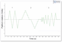
There are three separate paths the motor can take, which spin the test subject in different configurations. The first is a simple sweep, moving the platform back and forth. The second is a staircase path. This is similar to the sweep, except the platform will pause for a given amount of time periodically before continuing on. The third is also like the sweep function, but in this case, the platform begins by sweeping out small angles, and ramps up as it continues.
The code to run these modes is executed by the Arduino. The user selects their motor speed, iterations, and min and max angles and presses the "go" button. The User Interface then sends a series of data values representing these choices over the serial port by which the Arduino is connected. The Arduino is constantly listening for incoming data, so when it receives the series it determines which mode the user selected and executes the motor movement function.
Implementation and Testing[edit | edit source]
Testing and Implementation had not begun by project completion. The Twister has three unfinished components, the first being the positional potentiometer used in the motor assembly. A single-turn potentiometer was used to give feedback on the position of the turntable. The potentiometer was implemented into the motor system, but the data was skewed due to noise and unwanted feedback. The second issue was the power source used to control Twister. The motor and electromagnets had direct voltage connections off the 24V power supply, but the torque sensors and potentiometers had an operating voltage of 5V, so a 24V to 5V voltage regulator was used to step down the voltage. The voltage regulator had only a temporary 5V output, and a conclusion was made that the system needed a separate 5V source to control those components. The last missing components were an emergency stop and fuses to the electrical components to prevent total system losses upon a short.
Along with the issues stated above, testing and troubleshooting is still needed on the system. Because of the above, a team will be completing Twister and the Lateral Attachment over the summer, and Twister should be operational by September of 2016.
Team Members[edit | edit source]
| Picture | Bio | Discipline |
|---|---|---|
| Austin Steiner:
I am currently a senior in Mechanical Engineering at the University of Idaho. I was born and raised in Spokane, Washington and plan to stay close to the area after graduation in the Spring of 2016. I like to spend my time away from college camping, drag racing, and fixing just about anything. |
Mechanical Engineering | |
| Jacquelin Remaley:
I was born in Idaho Falls, Idaho and grew up in Pullman, Washington. Next fall I will be pursuing a PhD in Robotics at Oregon State University. I enjoy playing guitar, stargazing, and exploring virtual worlds. |
Mechanical Engineering | |
| Sally Mei:
I will be graduating in the Spring of 2016 with a Mechanical Engineering and History degree from the University of Idaho. I am currently interning at Schweitzer Engineering Laboratories. I enjoy eating ice cream and gummy bears! |
Mechanical Engineering | |
| Robert Regent:
I am from Concord, California and I am a Senior in Mechanical Engineering at the University of Idaho. I am currently working as a Team Lead in Research and Development for a software and hardware company based in Denver, Colorado. I plan on relocating to Denver after I graduate. My hobbies include snowboarding, fitness, and 3D printing. |
Mechanical Engineering |
Document Archive[edit | edit source]
Project Schedule[edit | edit source]
- Reports
File:2016 P3 ProjectInspiration.pdf
File:2016 P3 DAQUserManual.pdf
File:2016 P3 MaxonMotor.pdf
File:2016 P3 FutekTFF400.pdf
File:2016 P3 FinalReport.pdf
File:2016 P3 QuickStartGuide.pdf
File:2016 P3 TechnicalPresentation.pdf
- Meeting Minutes
|
File:2016 P3 FallMeetingMinutes.pdf |
- Other Project Documents
|
File:2016 P3 DFMEA Analysis.pdf |
