UI Steam Plant Measurement Systems
| The plant configuration | |
| Team Name | Rolling Timber II |
| Clients | Scott Smith |
| Instructor | Dr. Steven Beyerlein |
| Mentor | Sammy Stuhlman |
| Group Numbers | Faisal Alqudairi,
Michael Silk, Miyako Nakayama, Waleed Alsheikh, Zakaria Alghamdi |
| Duration | Summer 2018 - Fall 2018 |
The goal of the project is to measure and record the primary fuel variables for the wood fired boiler at the UI Energy Plant. The measurements can be used as inputs to automate the wood fired boiler combustion controls. Mass fuel flow of the wood chips, moisture of the wood chips, mass air flow, air temperature and air moisture flowing into the boiler are all necessary to optimize combustion.
Problem Definition[edit | edit source]
The objective of our capstone project as Rolling Timber II is an extension of previous work with the intent of generating an operating lab prototype that can enable full-scale implementation in the UI Steam Plant.
Team Rolling Timber I (the previous team) was able to design and build a prototype sensor for mass fuel flow and fuel moisture content. These sensors will need to be refined and then a measurement and verification process can either prove or deny the design concept. Additionally, the measurement of mass air flow, temperature and moisture content will need to be developed.
Background[edit | edit source]
The University of Idaho Steam Plant produces steam for heating and campus buildings and sidewalks, as well as chilled water from a lithium bromide system. Steam is primarily produced in a boiler burning sawmill waste known as hog fuel.
The wood fired boiler at the University of Idaho is driven by the combustion of wood fuel and air. Mass fuel flow of the wood chips, moisture of the wood chips, mass air flow, air temperature and air moisture flowing into the boiler are all necessary to optimize combustion. Operation and control of biomass boilers has been primarily done by plant operators manually.
As of 2018, the woodchip boiler consumes approximately $ 1,000,000 per year in fuel. This is a significant savings over alternative fuels (e.g. natural gas), but could be further improved by implementation of a feedback control system to more efficiently supply fuel and combustion air.
Currently, excess fuel is supplied to the firebox of the boiler. Mr. Scott Smith, the Steam Plant Manager, estimates that approximately a 5-15 % reduction in fuel consumption could be achieved by implementation of a feedback control system, reducing operating costs and improving air quality in the City of Moscow. In addition to these tangible benefits, no other known wood-fired boiler has yet implemented comprehensive feedback control system, so implementation of this type of steam at the UI Steam Plant would be a breakthrough in biomass boiler technology.
Specifications[edit | edit source]
Functional Specifications
•It is fine to use modified unit such as lbs/min or lbs/s, however, lbs/hr is a unit which is usually used in the plant.
•Source of woodchips: Cedar, Pine, and Fir (These are available in this area)
Mechanical Specifications
Spatial Requirements
•Implementation of devices (our design) should be require little to no modification to the existing system in the plant.
•The available space within the throat is 9” wide × 84” long × 26” long. (for mass flow sensor of wood chips)
•Round duct – 24” diameter (for mass flow sensor of air)
•Rectangular duct – approximately the same cross-sectional area as the round duct (for mass flow sensor of air)
Materials for the prototype
•Mild Steel is preferred by our client.
Mass flow measurement[edit | edit source]
Fuel Mass Flow Rate Concept[edit | edit source]
|
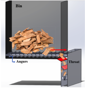
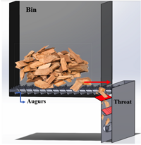
Wood chips thrown from outside usually goes into a large bin. These wood chips stay there for a while and get smashed into smaller pieces by augers (rotational blades). These smashed wood chips flow into a throat and eventually get burned in a boiler after they pass the throat. The possible location to install mass flow sensor is the upper side of the throat since all the wood chips need to pass through the throat. |
Idea behind the system[edit | edit source]
|
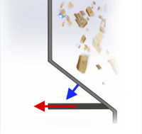
Impact plate: The possible design idea for the mass flow measurement system was impact plate since it can fit on the given throat dimensions and is mechanically simple. Whenever wood chips hit on the plate, it causes reaction force on the plate. Hence, this reaction force over time can be measured calibrated, which enables us to calculate mass flow rate [lbm/s] or [kg/s]. |
|
Design Concepts Considered We have two major concepts for design. 1• Design for the prototype-scale testing 2• Design for the actual implementation in the plant (full-scale)
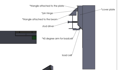
Requirement for the measurement plate design to success • Stick with limit availability area, because of the I-beam located under the bin. • The pivot point needs to be on the top left (above the I-beam), so we have the impact plate lay on the load-cell always. • We need to cover the two edges to avoid falling of woodchips outside the throat. • Load-cell arm need to be welded to bottom of the I-beam. • There is a rubber will be added between the arm and the impact plate, for better readings. • The supports will be attached to the top of the I-beam and the back of the impact plate. Additional to the design • We added a stud driver that goes the middle of the I-beam to the back of the impact plate. This driver will help to push the impact plate away in case we want to change or replace load-cell or the rubber band. |
Mass Flow Measurement[edit | edit source]
Software and Code
• NI LabVIEW (2018)
• DAQ Assist takes load cell signals in so we can record them in LabVIEW
• This system is calibrated to output a LBF signal.
Moisture content measurement[edit | edit source]
How moisture content works[edit | edit source]
|
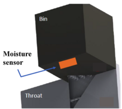
Moisture contents should be measured before wood chips go into the throat. (The reason for the target location for the moisture sensor installation, please refer to XXX). We assume that moisture content of the wood chips are all uniform for all the woodchips contained in the bin. Hence, moisture content measured from one specific location on the bottom of the bin can represent the moisture content of entire wood chips inside the bin. |
|
Drier the wood chips, better they gets burn, which is related to the efficiency of the wood-fired boiler. Hence, it is important to keep on track how much moisture contents wood chips have all the time. |
Idea behind the system[edit | edit source]
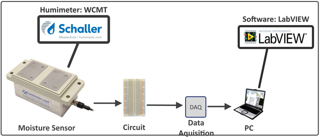
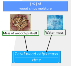
Moisture content can be calculated as [%]. WCMT-HGT: This sensor was from Schaller Messtechnik, which is a company in Austria. This can be installed stationary to measure the wood chips’ moisture, so we wouldn’t need major modification on the plant to install it. The nice thing about this moisture sensor is that the manufacture already provided the calibration table so that we can find moisture content [%] according to the output current we got.
Team Members[edit | edit source]
| Faisal Alqudairi
Major: Mechanical Engineering
| |
| Miyako Nakayama
Major: Mechanical Engineering
| |
| Zakaria Alghamdi
Major: Mechanical Engineering
| |
| Waleed Alsheikh
Major: Mechanical Engineering
| |
| Michael Silk
Major: Mechanical Engineering
|
