Unified Liquid Cooling Heat Solution
The objective of this Senior Design project is to design a thermal management system for a multi-kilowatt, multi-phase, power converter based around a unified thermal core with liquid cooling. This will require that the semiconductor transistor dies to be removed from the normal packaging found in a commercial device to maximize heat transfer to the thermal core and into the coolant. We will adapt a heat sink to the newly configured shape and use math models and simulation to fine the optimum design. After completion of this modeling we will be manufacturing a sink and then using experimental methods to determine the best option for our Heat sink to properly manage the systems waist heat as efficiently as possible.
| Unified Liquid Cooling Heat Solution | |
|---|---|
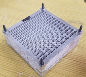
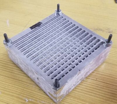
| Cross Hatched Heat Sink- Final Design Chosen For Solution | |
| Sponsor | US Navy |
| Team Name | Frigus |
| Team Members |
|
| Faculty Advisors |
|
| Mentor | Rachel Peterson |
| Duration | Fall 2016 - Spring 2017 |
Problem Statement
The objective of this Senior Design project is to design a thermal management system for a multi-kilowatt, multi-phase, power converter based around a unified thermal core with liquid cooling. –Rachel Peterson
The first phase of the process will be designing a heat sink to fit within the constraints for the thermal and physical properties defined by board configuration and MOSFET placement.
The second phase will be focused around testing for the purpose of refining heat dissipation, functionality, and efficiency.
Project Goals
Our Project Goals are to Complete a robust heat removal system to fit within the constraints required by the project. We will design the heat sink to be able attach securely to the MOSFETS with a pressure of at least 10 PSI.The current goal is to explore natural convection, if this is not feasible forced convection will be explored. We hope to be able to manufacture the Heat sink in house, but will evaluate all options. In addition we will preform tests and gather on the various sinks both as simulation and in an experimental capacity, with the aim of finding the optimal solution.
Design
Design Specifications
| Design Specifications Sheet |
|---|
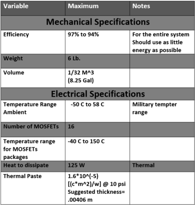
|
Heat Sink CAD Design
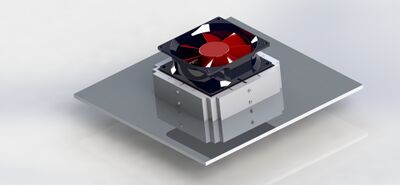
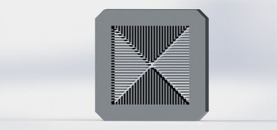
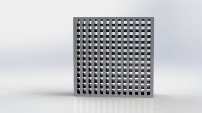
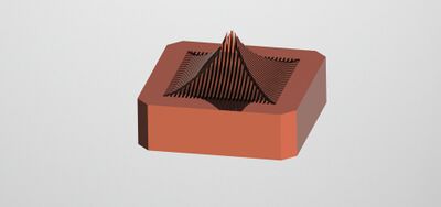
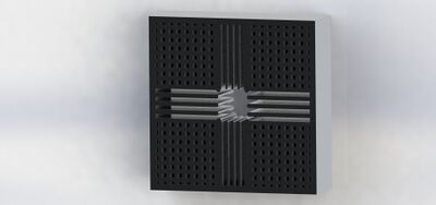
We began by making various solidmodels of our heat sink based on the mechanical specifications. We ended up with 4 basic models which we presented on the Snapshot day. We tried to maximize the surface area of the heat sink while deceasing the weight and making it machinable. Currently two of these models, the triangular design and crossed hatched fin design, are being simulated as potential candidates. If favorable data is found then machining will begin on each model.
| Trangular sink design | Crosshatched fin design |
|---|---|
|
|
| Pyrimid sink Design | Fin and Gap Design |
|
|
| A solidworks model of the how the whole piece would possibly look with board, heat sink, fan, and surrounding case. |
We have since narrowed down our designs to include the Triangular Sink Design and the Cross Hatched Sink Design. Later we expanded this to include the Cross hatched redesign as well.
Heat Sink Math Modeling and Simulations
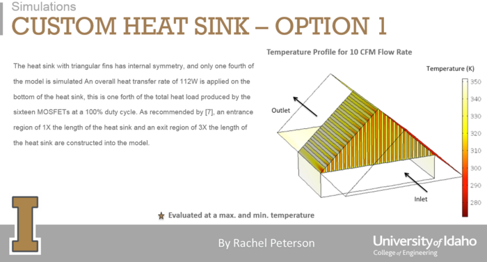
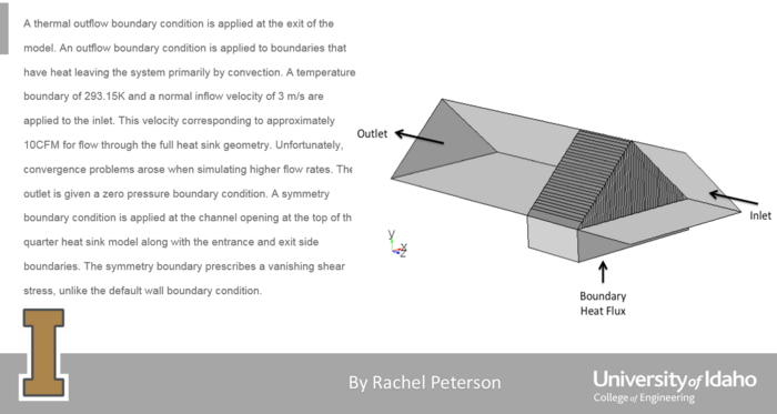
We began by creating models to determine how much heat the sinks would need to draw as well as how air would flow through them. Grad student Rachel Peterson has been modeling these designs and helping us determine there eligibility as working heat sinks.
| Preliminary Board Simulation | Model of Board with Basic Heat Sink |
|---|---|
|
|
Manufacturing
After choosing our Final Two Air Cooled Heat Sink Designs we began to finalize there drawing and determine how we would manufacture them. Later we expanded this to include the Cross hatched redesign as well.
Triangular Heat sink
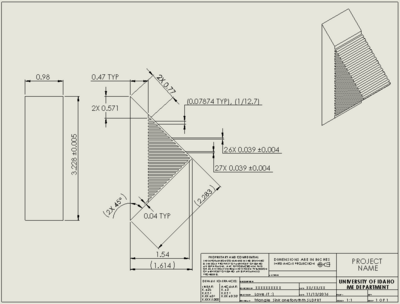
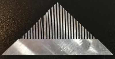
We began with the triangular heat sink using a slitting saw and manufactured one of the sides of the sink with the new blades, still using approximately 1 mm blades and .8 mm gaps. It worked well with only small user error in manufacturing. When manufacturing second side teeth on the blade broke off due to moving too fast through the material. The lesson we learned was that saw blade metal is extremely brittle and this plus the fact that our saw blades our incredibly thin means that ours are very easy to damage. This meant we had to take lots of care with how we manufactured the last few sinks.
| Triangular Sink Drawing | Triangular Sink | |
|---|---|---|
|
|
Cross Hatched Heat Sink
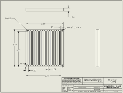
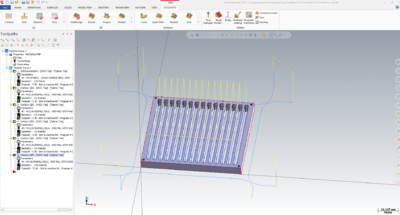
For the next iteration of the air cooled sinks we plan to look at our second design option. Originally we had narrowed down our designs to the Triangular air sinks, which we chose as the primary sink design and the slotted alternating sinks. We have found though, that the triangular sinks are very rigorous to machine as they take a lot of time and have little room for error. Therefore we began to look into the second design option as an option for testing. After a few modifications we came up with our final crosshatched heat sink design, based around the shops capability. We were able to crate a Mastercam code for the sink and then manufactured 4 of them side by side on the shops Hass Mill.
| Slotted Heat Sink Drawing | Slotted Heat Sink Mastercam |
|---|---|
|
|
Redesigned Cross Hatched Heat Sink
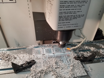
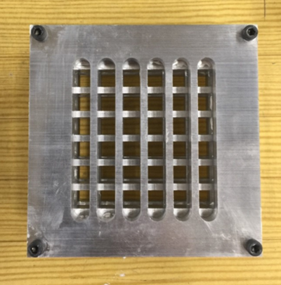
After making and testing the crosshatched sink we decided to do a redesign that would work better with a 2 fan configuration and better fit the air inlet. To do this we increased the fin and slot width and decreased the height, as well as decrease the number of slots and fins and draw then closer to the center. While this did add some weight, it also allowed us to make the sink better fit the second fan and reduce pressure loss, as well as better fit the boards air intake.
| Redesigned Cross Hatched Manufacturing | Redesigned Crosshatched Sink |
|---|---|
|
|
Water Block
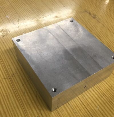
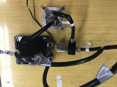
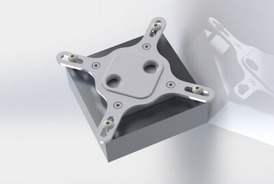
For the water cooling system we manufactured a block to attach the cold plate to. It was fairly simple to make and will allow us to attach the cold plate to the top and draw the heat out of the mosfets.
| Water Block | Water Cooled System |
|---|---|
|
|
Drilled Heat Sink
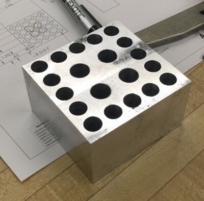
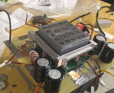
We were partway through machining our first air cooling system, when one of our partners in the project on the electrical side asked if we could make him a rough sink so that he could begin to test his setup for the MOSFET's and board. We brainstormed the quickest sink we could imagine manufacturing and then spend an afternoon in the shop quickly creating a drilled heat sink. So far it has appeared to meet his needs.
| Drilled Heat Sink | Drilled Sink In Board |
|---|---|
|
|
MOSFET Brackets
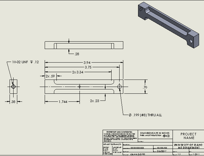
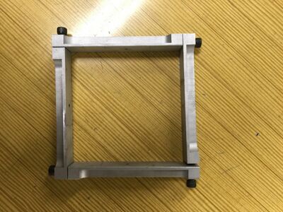
We ran into issues with attaching the MOSFET brackets. Holes in the block for attaching cold plate interfered with placement. So we came up with 3 designs to replace the old design. We finally settled on a design that interconnected the ends of each of the bracket sides. Next we drafted brackets in solid works then machined. So far it has worked well to secure MOSFET’s to the heat sink, although they did need to be altered once.
| MOSFET Bracket Drawing | MOSFET Brackets |
|---|---|
|
|
Case
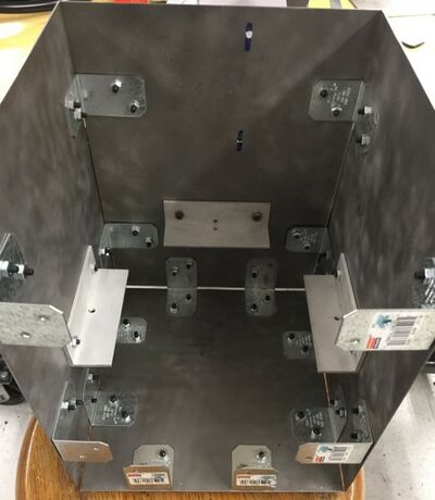
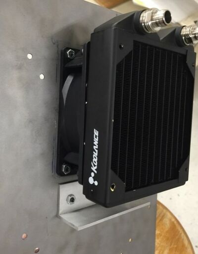
We designed using Solidworks. We used different brackets due to availability. Cut 20 gauge sheet metal to 8 x 12 in sheets for the sides and 8 x 8 for the top and bottom. Brackets connect the sides together as well as the bottom. Brackets were machined to mount and secure the board and the MOSFETS to the case.
| Case Manufacturing | Attaching components to case |
|---|---|
|
|
Experimental Designs
For our experimentation we planed to use a combination of thermocouples and thermal imaging cameras to best test how well the heat sink operates within the system. We planned to encase the the board and sink and using a controlled environment model how well each heat sink works. Test both systems (air and water) outside of the case in the senior design suite the temperature is relatively constant. We can establish basic ground readings and finalize testing steps and procedures. Thermal imaging as well as thermal couples places in key locations on the system will be used to gather data that can describe system variables. Variable and steady state power will be supplied to the MOSFETS to get multiple data points at involving different scenarios. The variables we are looking at include:
-System Variables Energy efficiency Steady Temp of the mosfets vs. time it took to get there Weight Maintenance
-Variables to measure during testing Power Input Heat Dissipation Thermal imaging Thermal couples
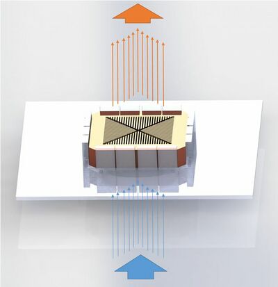
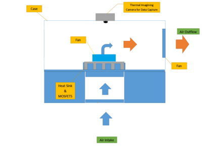
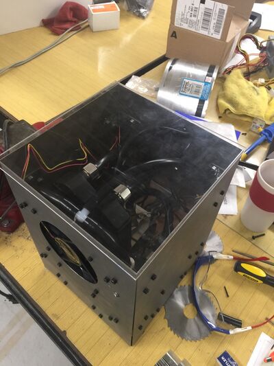
In addition we needed to look at how to balance and compare Air vs. Water Systems. Some possible modifications we might need to make after testing are aluminum/acrylic body, different brackets, case design to make modifications easier, and to change inlet outlet locations. Models such as the one shown below have been made modeling the case for the experimental design. The case for the experimental design is also shown. Overall the case was secondary to the main project and needed mostly for a testing apparatus.
| Heat sink and Board | Case for modeling |
|---|---|
|
|
| CAD Model of Case | Primary Testing Case |

|
|
Liquid Cooling
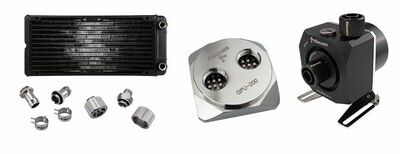
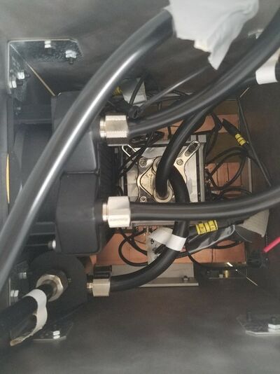
We eventually decided to try using a liquid cooled system if we didn't get favorable results with our air cooled system. We began looking into the alternative of a liquid cooled system and how we might implement one into our system. There are various considerations that needed to be taken into account if we switched to a liquid cooling system.These are: Mass Considerations- Switching to a liquid cooling system would greatly increase our weight. We planed to try to choose a design that minimized our added weight and stays within our limit. Leak considerations- Liquid cooling has a much greater risk of issues like leaks and pump failure. We plan to make sure everything stands up to durability testing. Size considerations- There was an added increase in size with new components being added. We planed to redesign the case to compensate for this increase in size and minimize it.
So far the water cooling system has been assembled, tested, and is functioning properly. The system was tested using 5 and 12 volt inputs and pumped water through the system which enabled greater flow rate. It works well with the water block and proved to work well in testing.
| Coldplate and block for liquid cooling | Some of the Parts that appear in a liquid cooled system | Water System in Case. |
|---|---|---|
|
|
|
Testing
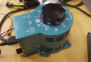
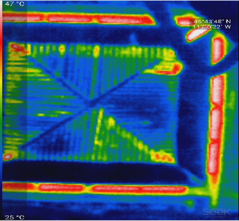
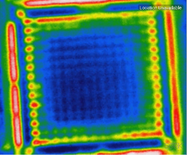
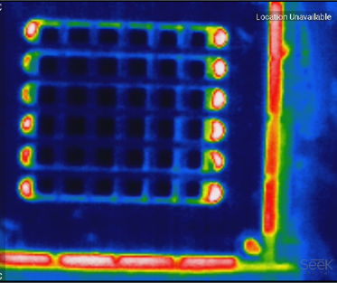
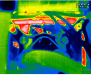
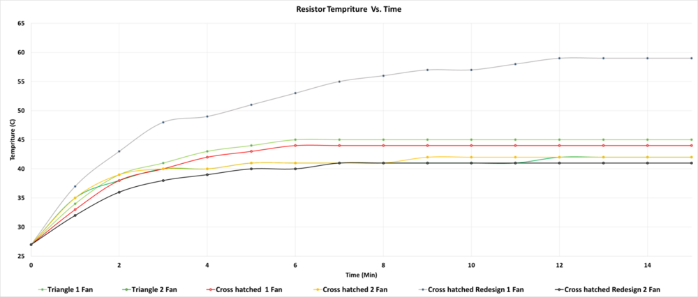
We began our testing shortly after finishing the manufacturing of our last set of heat sinks. We started by outlining our system and test variables, then began setup of the system before finally running the tests themselves. The tests were evaluated using a thermal imaging camera made by SEEK Thermal, capable of measuring -40 to 300 C. MOSFETS were unavailable for testing, therefore sixteen 4.7 Ohm resistors were used to simulate the heat released by the MOSFETS. Eight of the resistors were set up in series and in turn set up parallel with the other eight resistors. A type 3P variac power supply capable of either 140 or 120V supplied power to the resistors. Each test was run for 30 minutes to insure that the steady state temperatures was reached. Only one test was run for each configuration, the first being at 40 percent of 120V which allowed 7.66W per resistor. There were also tests to determine if there was a significant difference between having one fan pull air from the case or having two fans one pulling air from the case and another sitting directly on top of the heat sink pulling air through.
Testing Variables and Form Design
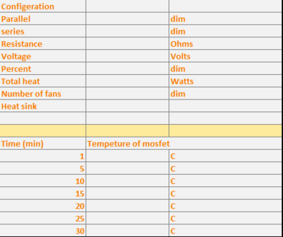
We began our testing process by defining our testing variables and creating a rubric for data recording and processing. One of the testing rubrics used during testing can be seen below.
| Testing Form |
|---|
|
Testing Setup and Equipment
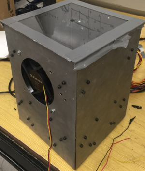
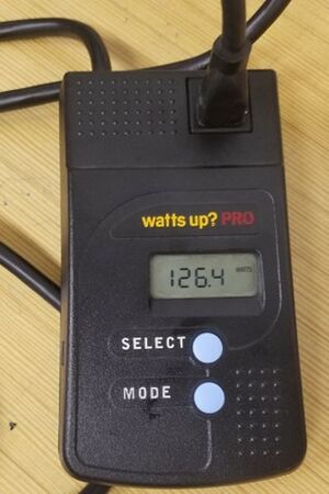
We then used a watt meter with a variac power supply to power the board at approximately 125 W, as well as a power supply to run the fans and pump. We then recorded 30 minute test segments using our thermal camera, ran at 125 Watts, and ran test on the air sinks using 1 and 2 fan configurations.
| Testing Case | Watt Meter | Variac Power Supply |
|---|---|---|
|
|
|
Testing Results
We compiled all test data, calculated thermal resistivity of each sink, and applied weights to test and system variables. We also characterized heat sinks by thermal resistivity, power draw, weight, and manufacturability and used that to determine that the Crosshatched Heat sink with 1 fan attached, was the most viable solution.
| Thermal Image of Triangular Heat Sink | Thermal Image of Cross Hatched Heat Sink | Thermal Image of Redesigned Cross Hatched Heat Sink | Thermal Image of Water Cooled Heat Sink |
|---|---|---|---|
|
|
|
|
| Plot of Test Results- Temperature VS Time |
|---|
|
| Calculated Thermal Resistivitys |

|
| System Variables | Final Heat Sink Chosen |
|---|---|

|
|
Team Members
| Member | Contact info | Discipline | |||||
|---|---|---|---|---|---|---|---|
| James Sutton (JT) | Sutt9939@vandals.uidaho.edu | Mechanical Engineering | |||||
|
JT is a senior in Mechanical Engineering. Raised in Haley, Idaho, JT enjoys skiing, rock climbing, and hanging out with his best friend, and mentor, Connor Trulock. | |||||||
| Caleb Jo | Jo7623@vandals.uidaho.edu | Mechanical Engineering | |||||
|
Caleb is a senior in Mechanical Engineering. He does things involving things and stuff revolving around other stuff. | |||||||
| Connor Trulock | Trul5964@vandals.uidaho.edu | Mechanical Engineering | |||||
|
Connor is a senior in Mechanical Engineering. Born in Ketchikan Alaska, Connor moved around as a kid, until finally graduating high school in Kamiah Idaho, then began pursuing an education at the university of Idaho. Connor enjoys hiking, reading, playing video games, and hanging out with his best friend, and mentor, JT Sutton. | |||||||
