Virtual Control System Network
| Team Name | vGrid |
| Duration | Fall 2017 - Spring 2018 |
| Faculty Advisor | |
| Client |
|
| Team Members |
|
Welcome to the wiki page for the Virtualization of Industrial Control Systems capstone project at the University of Idaho. Here someone can find all the information you need to know about the project, such as the background, specifications, design choices, team information, and document archive.
Project Overview[edit | edit source]
Background[edit | edit source]
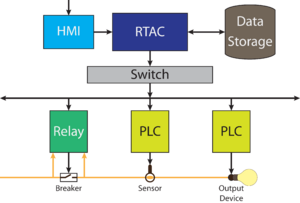
The goal of this project is to create a portable system for presentations about security in virtual control systems, which can be used as a test bed and demonstration platform for various industrial control system (ICS) devices. Previously this role has been filled in part by a physical system containing a relay, PLC, gateway, RTAC, and a HMI.
Problem Statement[edit | edit source]
The current physical system has two major drawbacks, flexibility and portability. Because the system is hard-wired with a fixed number of devices it cannot be reconfigured to run different types of simulations and presentations. This also means that as new technology comes out is difficult to implement it into the design. Although the previous system was designed with portability in mind, there is a limit to how portable a system can be while implementing physical devices. The bulk of the device means that it cannot be moved easily or brought on board a plane as a carry-on. This is an issue, as it limits the audiences it can be presented to due to the logistics of transport.
Problem Solution[edit | edit source]
By creating a virtual parallel of the previous model, we can have its full functionality while adding on key features. Because it will no longer be hard-wired together the new network will be reconfigurable with ease, allowing much needed flexibility. This also means that adding new devices and duplication of old devices will be quick and easy, allowing for large-scale complex networks to be created and tested. Because the entire system is virtual, it can be hosted on a remote server and accessed anywhere with an internet connection, making it as portable as a laptop. Additionally, this makes it easy to expand upon, even allowing for a hybrid network of physical and digital devices to be created for specific applications.
Project Goals[edit | edit source]
Below are listed the project goals of things that will be included in our virtual system
 - Relays
 - Gateways
 - Firewall
 - RTAC or similar device
 - Backend data emulator
 - Human Machine Interface
 - Communication channels between devices using industry standard protocols
 - Documentation to allow the project to be taken up by other teams in the future
Schedule[edit | edit source]
| 10/25/2017 | Project learning primarily completed |
| 11/15/2017 | Virtual relay prototype |
| 11/29/2017 | Human machine interface prototype |
| 12/6/2017 | Basic communication between relay and HMI |
| 12/15/2017 | Expanded virtual relay prototype |
| 1/17/2018 | Gateway created and basic networking achieved |
| 1/31/2018 | PLC prototype implemented |
| 2/14/2018 | Backend input emulator prototype implemented |
| 2/28/2018 | Polished networking and simplified setup |
| 3/14/2018 | Expanded documentation |
| 3/28/2018 | Stretch Goals and Polishing |
Design[edit | edit source]
Overall Structure[edit | edit source]
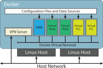
The infrastructure for this project will be a Linux server hosted externally (during development this will be on an Amazon Web Services hosted server, then during use it will be hosted on a server owned by PNNL for use and further development). We will use Docker containers for each individual component of the industrial control system. These component Docker containers will communication over a Docker Virtual Network using the modbus protocol (a common protocol used in industrial control systems). The infrastructure will be created such that in the future this can be extended to include other common communication protocols such as DNP3. To enable rapid deployment of docker containers we will be using Docker Compose, and Docker Swarm will be used to network containers spread across multiple hosts (to ensure created environments can be scaled as much as possible). Access into the network will be provided by a VPN container to ensure that the environment is realistically separated from other networks and to ensure security. Data will be fed into the virtual relays through a plugin system, to allow flexibility in what programs and methods can be used to generate or simulate data.
Relay[edit | edit source]
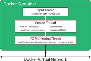
The relay will be written from scratch in C++. the basic structure of it includes three threads; an input thread, a communication thread, and a control thread. The input thread waits for a signal that there is input inbound. Once this signal is received, it wakes up the control thread and the main thread handles the data input from the data plugin. The control thread is the core of the program, and implements user-defined logic on incoming data. Based on this data, it will update the control state and push both the input data and control state to the I/O thread. The I/O thread has two main jobs, outbound and inbound communication. Data and the control state are pushed to the communication thread by the control thread, the communication thread must then package these up as modbus packets and send them to a control device. For inbound communication, the input thread is constantly listening for a control order from the control devices on the network, when one is received it is sent to the control thread so it can be acted upon.
Gateway[edit | edit source]
The gateway will be handled by Docker. Included in Docker's base features are simple networking devices, this is the easiest way to set up the network without creating a convoluted setup process.
Firewall[edit | edit source]
The firewall will exist on the edge of the network to ensure no improper communication enters or exists the network.
Back-end Input Emulator[edit | edit source]
This will feed data into the relays, and will be implemented as a plug-in. The data this feeds will be based off of real world data, obfuscated to protect privacy. There will be options to play a simple loop of data specified by the user, or to randomized the data even more, for random input to be used in network testing. The implementation is modular and documented so it will be easy to expand in the future with programs such as Opal RT (an industry standard program for feeding test data to industrial control systems).
Human Machine Interface[edit | edit source]
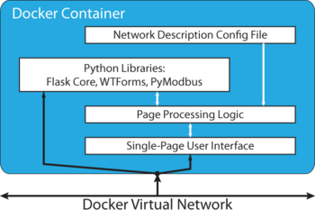
The Human Machine Interface (HMI) will be created with a simple base developed using python with flask and pymodbus for communications. The HMI will poll devices (such as relays) for data to display. It will have a simple file system to enable caching of information such as slave device IP addresses, and to enable other convenience features. The HMI can also send commands to devices on the network. For example, it can send an interrupt request to a virtual relay to manually flip a breaker. This functionality can be added for each new type of device on the network, so the HMI can be configured to seamlessly interact with any device added to the simulation. To add a new type of device to the HMI all that you need to do is expand the JSON file that it reads device types from.
Virtual Private Network[edit | edit source]
The Virtual Private Network (VPN) will be a docker container that allows the network to be accessed in a safe and secure way. You will be able to access the network either remotely or locally through the VPN container, with security set up as a password or with a public/private key combination. As mentioned earlier, this will allow for realistic modularity and improved security of the virtual network.
Configuration File Generating Script[edit | edit source]
In order to generate the configuration files for devices such as the PLC and HMI, we will have a script on the network. The script will run immediately after Docker Compose sets up the network, discovering the devices it creates to compile all the data each device will need in their configuration files. This will be done through Docker's Python API, by taking advantage of the services and tasks Docker Compose sets up to keep track of individual containers (this will allow us to set up multiple different containers with the same configuration settings, reducing some of the tedium in setting up a large network of similar devices). Next, the script will output this data in the format that each different device is able to read. These files will then be loaded through Docker Volumes onto each individual container that requires them, and an update will be forced in each of these containers. The reason this is needed is there are some things that are dynamically set when launching a network with Docker Compose, such as IP addresses, this reduces the need to have someone manually set all these such configurations by hand. Additionally, it allows for different configuration "profiles" to be made for different types of devices and is able to auto detect them, so their configuration doesn't need to be copied multiple times through each configuration file.
Design Testing[edit | edit source]
Throughout the process of development we continuously tested our design, opting for an agile development approach. We did two main types of testing, integration and unit testing; however, some devices cannot be proven to operate without others (such as the networking of the docker network) so the line between these two types of testing is blurry. We will not worry too much about where to draw the line here, instead the testing will be loosly grouped into integration tests and unit tests based on where they seem to fit best.
Integration Testing[edit | edit source]
We set up a network with a Vrelay, an HMI, and a VPN. We were able to connect with the host through the VPN to the HMI. Once connected to the HMI, we were able to poll the Vrelay mandually and automatically for information. The Vrelay was set to have an input alternating between two different discrete input sets. We were able to see this input changing and being sent to the HMI. Additionally, we were also able to send a trip signal from the HMI to the Vrelay, read that the trip signal worked from the HMI, and reset the trip signal from the HMI.
This is also the demo that we ran at our last Snapshot day to show our progress.
Vrelay[edit | edit source]
We set the Vrelay up on its own as a Docker container, we were able to probe it with a Modbus testing program and see that it responded correctly. This was also verified to work with pymodbus. Through the Modbus testing program, as well as pymodbus, we were also able to trip and reset the trip state over a network. Multithreading was checked using mutex statements and with standard testing for race conditions, taking into account edge cases. This ensures that the threads shouldn't get locked during operation.
HMI[edit | edit source]
We loaded the HMI as a docker container by itself and ensured that we could access the page it was loading. Through the interface we could tell that it successfully loaded the configuration file on startup, as well as when the reload button is manually pressed. We also set the HMI up on a network with a Vrelay and ensured that it was able to read data from it, as well as refresh manually to read the data.
Docker Swarm[edit | edit source]
We ensured Docker Swarm was operating correctly by checking its deployment over multiple hosts. We set this up with some random Docker containers and checked that they could all see each other as expected.
Docer Compose[edit | edit source]
We tested that Docker Compose created containers as expected when launched, and would create varyining amounts of containers as specified by the .yml file used to launch it. We were able to verify this by using the Docker Python API, as well as through command line Docker.
Documentation[edit | edit source]
We ensured that our documentation works when followed by running thorough it from scratch after finalizing it. This was done on both a bare-metal Debian installation, as well as on an AWS machine. This ensures that any issues with virtualization or drivers that aren't due to specific implementation were caught.
Team Bios[edit | edit source]
| Joey Chereck Computer Science |
Gabe Gibler Computer Science |
Ben Merritt Computer Science |
|---|---|---|
| Bio: Joey is a Computer Science student from Kirkland Washington. He is a member of the University of Idaho Cyber Defense team, and enjoys rock climbing and backpacking in his free time. |
Bio: Gabe is a man of mystery with years of experience working in professional IT and web development. In his free time he enjoys long bouts with Compilers assignments and martial arts. |
Bio: Ben works for the University of Idaho as a systems administrator, managing servers used for research. In his free time he enjoys exploring new programming languages (Rust is a favorite of his), and amateur radio. |
Contact[edit | edit source]
Ben Merritt (merr4001@vandals.uidaho.edu)
Gabe Gibler (gibl3465@vandals.uidaho.edu)
Joey Chereck (cher3222@vandals.uidaho.edu)
Jessica Smith (jessica.smith@pnnl.gov)


