Battery Ultracharger
| First Prototype | |
| Sponsors |
|
| Team Name | UltraCharge |
| Duration | Spring 2016 - Fall 2016 |
| Faculty Advisors | |
| Students |
|
The goal of the project is to create a device that can gather enough energy in two minutes to charge a cell phone. This product is intended for travelers who are short on time and need to recharge their devices, namely a cell phone. This device should be portable.
Problem Definition
When people travel they tend to not have a lot of time between connecting flights or when they're on the go. But if their electronic device dies or is low on energy then people run into a problem. If people had a device that could charged in two minutes or less and then be used to charge your cellphone it would make the stress of traveling less.
Deliverables
A device that can charge in two minutes or less and store enough power to charge a cell phone.
Specifications
- Design Specs
- Length: 6" to 8"
- Width: 4" to 6"
- Thickness: up to 0.75"
- Weight: Approximately 7 oz
- Electrical Parameters based
- Capacitance of around 165 Farads
- Energy Storage: 9.5 Whr - 11.5 Whr (enough to charge a cell phone)
- Charge Time: 2 minutes or less
- Amperage Intake: 20 Amp Max, Lower End of 17 Amps
Project Learning
Client Interview with Dr. Hess
- List of questions about project (technical, general, financial, and miscellaneous) were asked and recorded.
- These questions and answers were the basis of our project. It's what guided us in the right direction.
- File:Client-interview-dr.pdf
Instructor Meeting
- Meets every Thursday in the NASA Conference room (3rd floor of BEL) at 4:30
- Here we discuss how the project is going and what has happened during the week. An agenda is created before the meetings to keep the meeting on track.
- Discussions range from technical aspects to due dates to finances of the project.
Calculations
Energy storage in capacitor equation. This equation is used to calculate the capacitance needed for the required for the capacitor bank.
Joules=1/2*(V)^2*C
The voltage is the voltage rating on the capacitors.
Testing
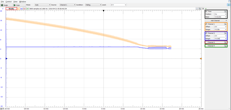
This graph shows the capacitor bank charging a cellphone until it can not supply the appropriate voltage for the buck conveter
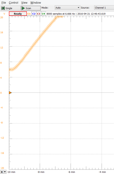
This graph shows the capacitor bank charging at 6 amps. We can get a full charge in about 4 minutes so in creates the amperage will give us our goal of 2 minutes.
Design
Buck Converter
For this project, the overall design is based on a buck converter in order to reduce the high input voltage to a lower one while maintaining the current. As such, this layout leads to the necessary adjustments for when charging the supercapacitors on the other end of the circuit. Through a pair of N channel power mosfets, the flow of power is regulated by cycling on and off in its delivery to the load, in this case being the supercapacitors. These swap between off and on between each other, allowing for no slips as to when a section is energized or not, as one controls the flow from the rectified input and the other is associated with the buck converter diode.
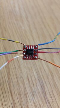
Gate Driver
High voltage and current flowing through the circuit means finding ways to power the gates of our mosfets were more difficult than usual. A high source voltage meant a gate voltage nearly just as strong was required to flip the switch and turn the mosfet into the "on" position. As most drivers are built to handle small voltages of several volts at most, finding a dual-gate driver in the vein of a motor driver was realized as a more achievable option. This decision was what lead to the second mosfet being added in series with our buck layout's diode.
Capacitor Bank
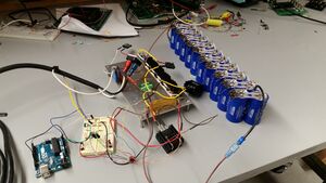
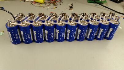
Formed with 20 identical supercapacitors, our bank is designed to optimize the capabilities of the capacitors and achieve the energy storage at the level and speed at which power is pumped into them. This optimization is seen through the ten pairs of parallel capacitors set in series in order to accept even greater levels than the input voltage.
Microcontroller
Through an Arduino Uno, we control the switching of the gates via two readings across a resistor just before the power enters the supercapacitor bank. By detecting how the voltage level between both sides of this resistor, the microcontroller reacts by sending a signal to open or close the gates of the mosfets.
This boils down to the controller adjusting the system based on how much current is flowing into the system. In a way that is comparable to filling a pool with a bucket, the controller senses when the current builds to a certain point and then switches the mosfets in order to dump the current load into the supercapacitor bank. This process repeats constantly, allowing for the bank to build up its total energy over time.
Team Information
| Keith Leitner | Interests: Power and Microelectronics |
| Electrical Engineering | |
| Email: leit1770@vandals.uidaho.edu | |
| Robert Prew | Interests: Power and Electronics. |
| Electrical Engineering | |
| Email: prew9256@vandals.uidaho.edu |
