Campus Facilities Microgrid Expansion
| Team Name | The Facilitators |
| Duration | Fall 2019 - Spring 2020 |
| Faculty Adviser |
|
| Mentor |
|
| Client |
|
| Team Members |
|
This project aims to provide insight and models on how to expand the existing microgrid on campus to include the future generation capabilities of steam turbines and a PV solar array to support critical loads and maximize efficiency within the microgrid. Our analysis will reveal pertinent issues associated with the expansion of the microgrid and will expose the pros and cons pertaining to the capacity, connectivity, protection, and overall efficiency of the grid. We will also highlight the best suited technology for these applications.
Introduction[edit | edit source]
Background[edit | edit source]
A capital project to install steam turbines to the campus energy plant for power generation is currently underway thanks to the help of multiple senior design projects. The turbines will be the basis for the first microgrid on campus to reduce energy costs and support critical loads during power outages. The overall UI microgrid scope includes the entire campus, with a total of 143 floors, excluding Northern farms. The current generation for the campus microgrid includes the steam turbines and the solar panels that will be placed on the roof of IRIC. This project will expand the microgrid further to include a utility scale solar PV array of approximately 1.0 MW in size. With these sources of generation connected into a microgrid, we will be able to keep critical infrastructure on campus running in the event of the grid going down.
Problem Definition[edit | edit source]
- Microgrid should be able to sectionalize different portions of the grid based on prioritization, load demand, and available generation
- Determine the type and location of equipment needed to expand the microgrid
- Analyze microgrid performance associated with the peak energy available from sources accounting for seasonal changes in capacity
- Conduct an economic analysis
Design Goals[edit | edit source]
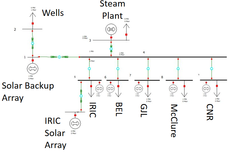
1. Expand the current campus microgrid design to integrate the new solar generation from the 1 MW array, the IRIC array, as well as the critical load of the wells.
2. Relays, switches, and controls will be tactfully integrated to ensure effective grid diagnostics and controllability. (Islanding/Load Shedding)
3. Determine which loads can be supported given available generation and under specific use case scenarios.
4. Account for seasonal changes and their effects on energy efficiency.
Microgrid Design[edit | edit source]
Design Considerations[edit | edit source]
- We are using Powerworld to simulate the expansion of the microgrid
- We are including the PV solar array from the Solar Backup Power Generation senior design team.
- We are taking advantage of the backup generators within buildings
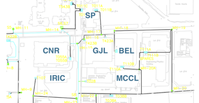
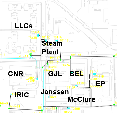
- The current setup of the microgrid includes the UI Steam Plant, McClure, CNR, GJL, and BEL.
- The current generation in consideration for the microgrid includes the UI Steam turbines and the solar panels to be placed on the roof of the IRIC.
- We will need to include the Solar Backup Power Generation's PV array and additional backup generators at certain locations
Specifications[edit | edit source]
- Generation for use:
- UI Steam Plant Turbines
- IRIC Solar Array
- Solar Backup Power Generation Array
- Backup Generators
- Loads to consider:
- Janssen Engineering Building
- College of Natural Resources
- Buchannan Engineering Lab
- McClure Hall
- Wells
- IRIC
Powerworld Simulation[edit | edit source]
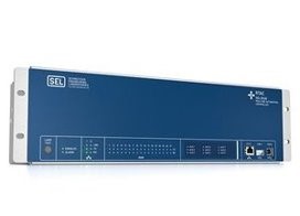
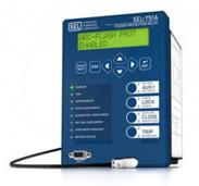
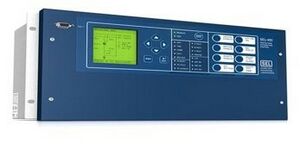
We will be using PowerWorld to simulate the expanded microgrid. The decision to choose PowerWorld instead of following what the previous team did, using the Real Time Digital Simulator with SEL relays and an RTAC, was done because of how much more can be accomplished with PowerWorld. We will be able to verify the previous team's design while also including different types of analysis. This program will also allow us to easily add onto our design and to change the data within the simulations. We will be able to test different use cases within PowerWorld including a worst case scenario and steady state operation.
The following are the various different simulations that we completed:
- Power flow analysis
- Load shedding simulation
- To verify what the previous team has done and to also include the new critical load
- N-1 contingency analysis
- An analysis of what would occur in the microgrid if one element was lost
- Fault analysis
- Seasonal analysis
- Optimization of equipment allocation
Validation[edit | edit source]
Power flow Analysis[edit | edit source]
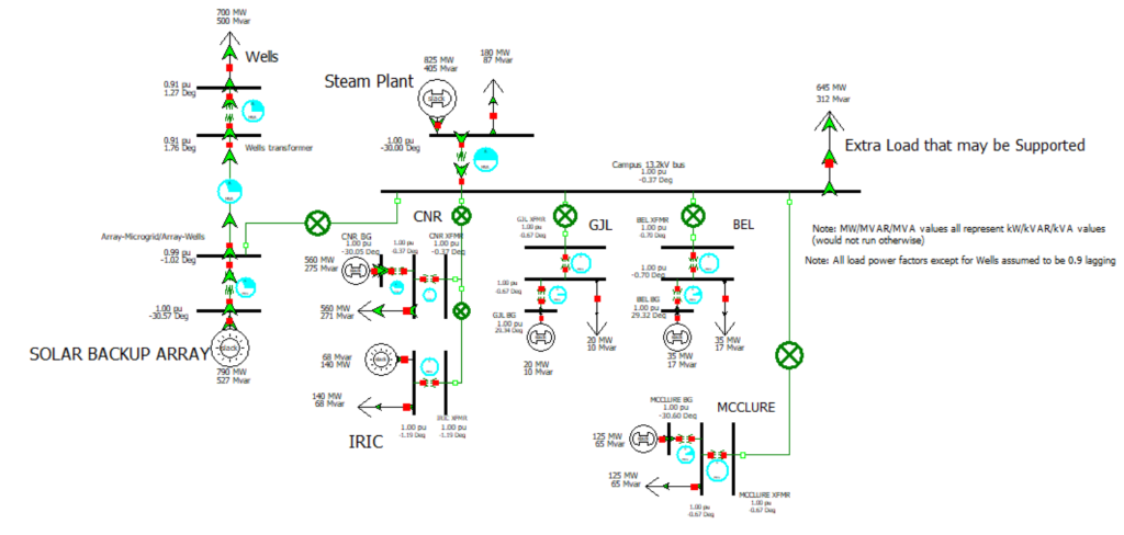
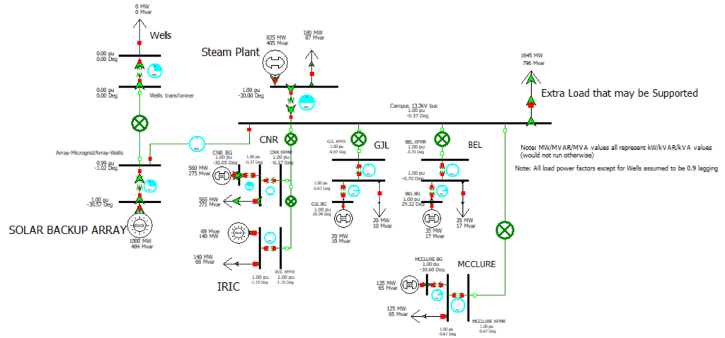
For the power flow analysis, there are two different cases that we simulated, the best-case and worst-case scenarios. Both power flow analyses were done under the assumption of rated equipment values and a 0.9 lagging power factor for building loads The worst-case being when the critical loads of the wells will need to be fully powered for fire suppression. Under the circumstances of the backup array being insufficient due to lack of sunlight or other failure, loads can be shed and power from the Steam Plant, backup generators, and the IRIC solar array can be harnessed to support the full loads of the wells.
The best-case being when the well pumps need no power and the excess generation can be used throughout campus. There will be a total of 1.645 MW of excess power.
Seasonal Analysis[edit | edit source]
For the seasonal analysis, we used data given to us by Facilities and the Solar Backup Generation team to simulate power flow analysis at each month, starting in January. The seasonal analyses were done at normal operating conditions, with the microgrid islanded from the power grid.
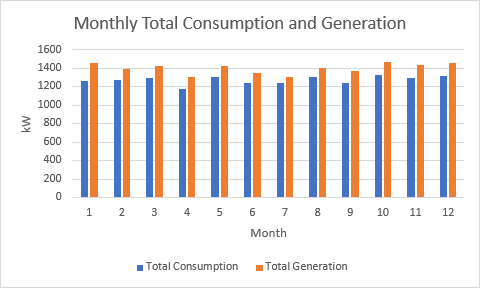
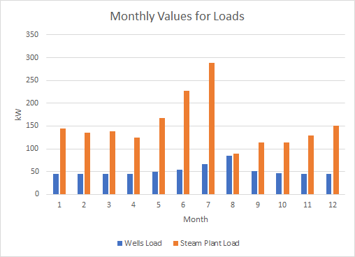
The following graph showcases the total load consumption and generation for the entire microgrid design. This includes the backup generators, the noncritical loads, and the losses of transmission lines and transformers. The total consumption is from the noncritical and critical loads currently included in the microgrid design as well as the losses due to the transmission and transformers calculated by Powerworld. As seen in the graph, we will have excess generation while islanded from the grid and in the best-case scenario.
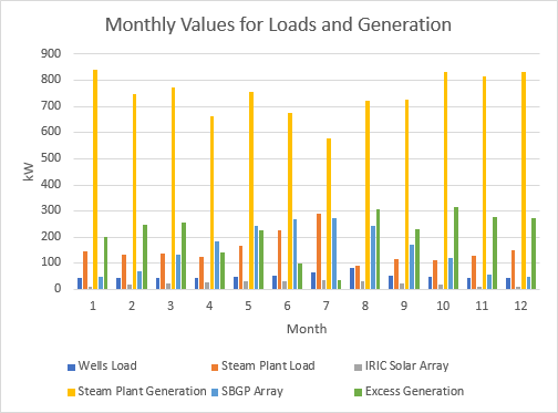
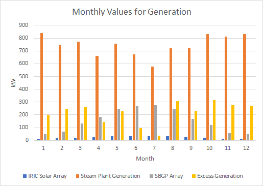
The following graph shows all the different sources of generation and loads that we deemed important and critical.
Since the wells do not normally take much power to operate, there will be excess generation during all months of the year. When both wells need power is when issues will start to occur, and load shedding will need to be implemented.
The monthly generation values showcase that the steam plant will be the main source of generation. Since the backup generators do not change depending on the month or season, they were not included on this graph. The excess generation shown in the above graph is calculated from the total consumption and total generation from the entire microgrid design in a best-case scenario.
Fault Analysis[edit | edit source]
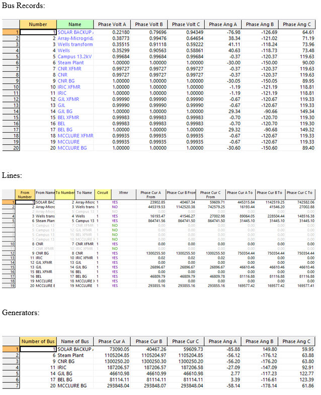
The fault analysis provides a selection of switches, as well as the setting of relays and stability of the system operation. This analysis evaluated the faults at each of the individual bus fault generation source (IRIC, Steam Plant, and Solar Backup PV Array). Each analysis from the generation source consisted of a line to line and a line to ground fault. Depending on the generation source there is a small difference of about 0.8 phase voltage difference. Each analysis shows not only the fault voltages and phase angles but also the fault currents and phase angles. Shown below is one of the fault analyses, Solar Backup Array – Bus Fault – Single Line-to-Ground.
N-1 Contingency Analysis[edit | edit source]
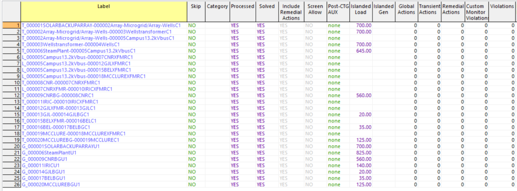
For this analysis, we will have a failure of one element in the microgrid and then analyze how the missing element will affect the rest of the microgrid. The elements can be transmission lines, generators, solar arrays, or buses. Shown below are results from disconnecting the transmission line between Campus 13.2kV bus and connection with every building including Array-Microgrid/Array-Wells bus.
For the Label column, it shows the actions we did, and also, we can clearly see the action at the bottom right table when we select any label in the table. For the violation column, it completely shows ‘0’, it means the system has no overloaded line, what if it shows ‘1’, then it means there should have overloaded lines. For the islanded load column, it means when you disconnect one element, you will loss the corresponding power, like the first row, if we disconnect the transformer between solar backup array and Array-Microgrid/Array-Wells, then we will loss 700 MW power.
Load Shedding Analysis[edit | edit source]
For all electrical equipment, there is a rated voltage, but in practice, it is not completely guaranteed to work at the rated voltage, which is a range around the rated voltage, generally required to be ± 10%. In order to protect the electrical equipment and process quality, if the voltage is lower than -10%, it is "undervoltage". When the operating voltage drops below this voltage, the protection action will cut off the power supply.
Equipment/Budget[edit | edit source]
This budget is taken as the constant costs, such as the price of cable per foot that needs to be run underground within the 1-inch conduit. Due to code standards 40 conduit can be run underground, but 80 must be run above ground. Most of the conduit will be run within the steam tunnels but for what isn’t it will be a variable cost. What makes it a variable cost will be the cost of labor, cost of equipment, as well as how many feet will need to be dug up to code standards. The other main variable cost consists of what type of landscaping and concrete work will need to be done. On the right side of the sheet above you have the total fixed costs, with your cost of risk insurance being 1% of the total fixed costs. The total cost was also adjusted with taxes as well as inflation of up to 15% to give a more accurate representation. The only cost during this project consisted of the EXPO poster.
Team Members[edit | edit source]
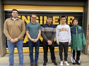
| Christopher Cervino
Major: Electrical Engineering
| |
| Shaun Andrews
Major: Electrical Engineering | |
| Ziyu Qian
Major: Electrical Engineering | |
| Huiyu Zhao
Major: Electrical Engineering | |
| Shawn Naughton
Major: Electrical Engineering |
Additional Documentation[edit | edit source]
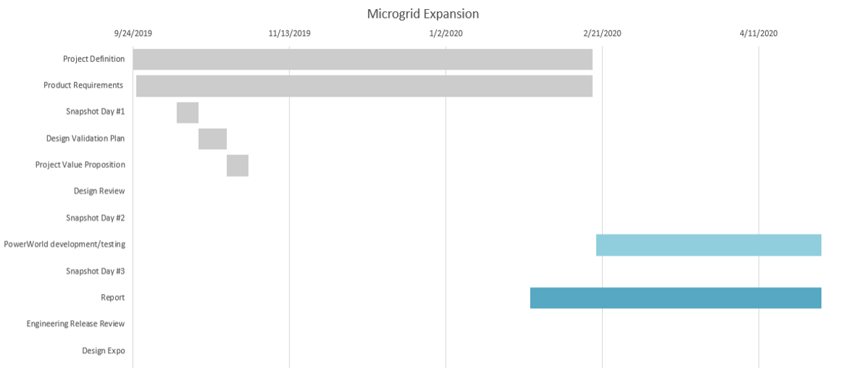
Project Schedule
Meeting Minutes
File:2019-09-10 to 2019-12-03 Team Meeting Minutes.pdf
File:2020-01-27 to 2020-03-02 Team Meeting Minutes.pdf
Presentations
File:Design Review 1.pdf
File:ECE 480 Design Review 2.pdf
File:Facilitators EXPO Presentation.pdf
Report
