Concentration and Storage of Solar Energy in Mining Facilities
| Sponsors | BiMBy |
| Team Name | Solar Rocks |
| Duration | Fall 2018 - Spring 2019 |
| Faculty Adviser | Behnaz Rezaie, Ph.D., P.E. |
| Mentor | Mellissa Bogert |
| Client | Ray Donelick |
| Team Members |
|
Our project is to develop a testing bed that will help determine the feasibility of storing solar energy within a mining facility. Mining operations leave behind a plethora of usable materials such as mined waste rock, overburden and/or tailings, Carbon Dioxide and large amounts of usable land. We wish to take these leftover materials and put them to use storing solar energy.
Problem Definition[edit | edit source]
Active and legacy mine sites in the United States present many large-scale environmental challenges. Active mining requires permits that require mine development and closure plans that adhere to strict environmental regulations regarding water, land, and habitat resources. Many legacy mines were closed prior to enactment of modern environmental regulations, and they have since become large-scale sources of land and water contaminants. At some legacy mines, contamination of nearby land and/or water resources will continue into perpetuity without large-scale site reclamation.
All mines ultimately close once the ore is exhausted either due to total removal by mining or loss of value. With mine closure comes loss of mining jobs.
A profitable nexus may exist between the mining industry and the renewable energy storage industry. In this project we ask the question: Can the heat from concentrated sunlight be efficiently stored in mine waste rock, overburden, and/or tailings? Active and legacy mine sites contain billions of tonnes of mine waste rock, overburden, and/or tailings in the USA alone and many more billions of tonnes worldwide. The next few decades are expected to experience a huge increase in demand for grid-scale storage of intermittent renewable energy sources such as solar and wind, and we think this could be a solution.
Background[edit | edit source]
Ray Donelick approached the University of Idaho seeking assistance in designing a small scale solution. Ray envisioned a system to focus solar energy and store the heat generated inside of a back-filled mining pit. Solar collectors will focus the energy on a receiver carrying Water. The water will then pass through a heat exchanger depositing the energy into Carbon Dioxide, one of the major pollutants from fossil fuel energy generation. the hot carbon dioxide will then run underground to the thermal storage container. This container consists of a insulating outer barrier with mining waste rock on the inside. The carbon dioxide will run into the thermal storage container and deposit the heat into the mining waste rock where it can be stored for long periods of time. Once the energy is stored, the consumer can tap into the available energy when solar energy cannot be readily collected.
Deliverables[edit | edit source]
The deliverables for this project is a complete testing bed to provide a proof of concept. The parts that will make up this testing bed are as follows:
- One in-line air heater: This will heat take the place of a solar collector for testing purposes.
- One pump: To move air through the thermal storage system.
- Piping system: This will allow us to direct air into the testing or control chamber.
- The thermal collection testing chamber: to perform various experiments and collect temperature data on heated rocks.
- Temperature collection system: this will consist of a thermocouple array to collect temperature data along the chamber length.
Common Terms[edit | edit source]
Since this project is related most specifically to Mechanical Engineering, I have attached a description of some common used terms.
- CFM - Cubit Feet per Minute: This is a common unit for volumetric flow rate. It is defined as the volume of a liquid moved through a piping system in a certain time [ft^3/minute].
- Working Fluid: The Fluid (air, water, etc) that is being heated up and cooled down. They are called working fluids because for our purposes, transferring heat is the "work" we need done.
- Static Pressure: This is a term used in pumping systems. It is defined as the pressure required to move a fluid through a pipe. All pipes have friction, bends and other areas that cause the fluid to slow down. The static pressure accounts for all of these and tells the engineer how to properly choose the required pump.
- PCB - Printed Circuit Board: This is a device commonly used in almost all electronic devices. A printed circuit board is green in color (usually) and contains all the wire connections for a device in printed layers. The required components are then attached to the correct spot and the device can operate without any external wires. These are commonly used because of how efficient the board can connect devices rather than running wire. Without a PCB your phone may still be the size of a brick.
- CSV or TXT files: These are very basic files where data is generally written to. They can be used to create code, but in our case they are files that many software can read information from. When you make a list in Microsoft Notepad and save it, you are saving that list as a TXT file.
Specification[edit | edit source]
As this is a testing bed, we want to be able to apply a wide range of values for fluid temperature and delivery. We also wish to construct the system as close to real-life conditions as possible and collect accurate temperature data for various experiment run times. Below are some general requirements of the system.
Thermal Chamber[edit | edit source]
The thermal chamber must be able to perform under the following conditions:
- Contain 2 meters cubed worth of gravel.
- Be assembled from basic construction materials.
- Be able to be modified for various experiments.
- Withstand temperatures of up to 600 Fahrenheit.
- Not allow the working fluid to leak from the system.
In-Line Heater[edit | edit source]
The in-line heater must be able to perform under the following conditions:
- Heat the working fluid within a range of 200-600 Fahrenheit.
- Be compatible with the selected heater control method.
- Be compatible with the selected piping system.
- Be able to operate on standard household electrical circuits.
Air Blower[edit | edit source]
The air blower must be able to perform under the following conditions:
- Operate at fluid temperatures between 200 and 400 Fahrenheit.
- Supply the required static pressure to allow fluid flow through the chamber.
- Be compatible will the selected piping system.
- Be able to operate on standard household circuits.
Data Collection System[edit | edit source]
The data collection system must be able to meet the following requirements.
- Collect temperature data with a total accuracy of one degree Celsius.
- Collect data at multiple locations within the test chamber simultaneously.
- Store large amounts of data in a usable format.
- Collect data for large experiment run times.
Design Considerations[edit | edit source]
There are several large considerations we have had to deal with. The biggest considerations are as follows:
- All our equipment must be able to run on standard household 240-Volt/120-Volt power.
- All materials used to construct the testing chamber must be commercially available at most department stores.
- Piping materials and sealants must be able to withstand the temperatures of the working fluids within them.
- Temperature and pressure wires and connections must be able to be buried within the chamber.
- The data collection system will have to store data for long periods of time, preferably within a CSV or TXT file.
Project Learning[edit | edit source]
Our main purpose for this project was to concentrate solar energy and store it in a test system. However due to cost issues we were not able to acquire a solar collector. The scope of our project then changed to the design of the testing bed and building a scale model. I have attached the latest system diagram below. The testing bed requires a thermal chamber, an in-line heater, an air blower, an air compressor, and several globe valves. The following sections will describe the learning associated with each part of the project.
Solar Collection System[edit | edit source]
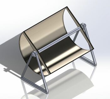
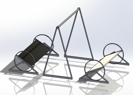
The largest component of our project was a solar concentrating device. This would focus sunlight into a single line where it could heat the working fluid. These devices are readily available and come in several different configurations. Solar troughs use a parabolic trough to focus the sunlight to the central point. These tend to be the most efficient but are the most expensive and most susceptible to weather. Linear Fresnel Mirrors act like a parabolic trough, but use an array of flat mirrors to imitate the parabolic curve. This creates less weather susceptibility at the price of efficiency. Both of these ideas were considered and two major problems arose. One, the size of these devices varies, but is no smaller than 70 squared feet. This is larger than we had room to house. Another issue was the cost. A single system at 70 square feet came with a price of $10,000 which was well outside of our budget. For more information on these systems, click the links under the pictures below. For more information on concentrated solar power in general click here.
Thermal Chamber[edit | edit source]
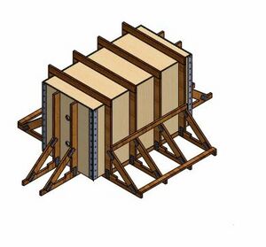
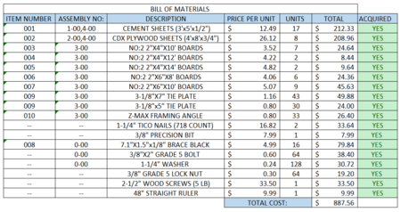
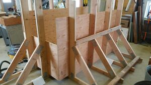
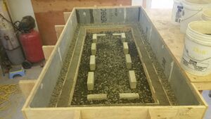
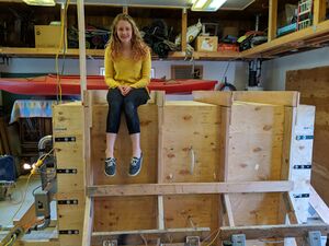
Since a solar collection system has its own inherent difficulties, we decided to focus more on the thermal chamber aspect of the project. Our current restrictions are mainly size orientated. We have been allotted a space of about 15X15X10.5 feet to house the chamber and all components. We chose to go with a long, double pipe chamber. This will allow us to have a control and experiment path. The chamber will be accessible from the top via a removable lid. We also decided to construct this chamber from lumber and cement board. This will allow for simple construction and immediate access to materials. The 3D-model of our testing chamber is shown on the left, and the bill of materials for constricting the chamber are on the right. The constriction plans are available here.
In-line heater[edit | edit source]
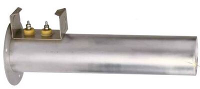
A in-line heater will take the place of the solar collection system for our testing. We need a heater that can heat air to temperatures comparable to that of a solar collector. We purchased a heater from the supplier OMEGA. The heater can heat air up to 600 Fahrenheit and runs off of either 240 or 120 volt power supply. A controller will be installed in line with the heater so we can choose a desired inlet temperature. The heater is rated for up to 200 CFM volumetric flow and can supply 500 to 2400 watts of energy to the air. For more detail about this specific heater, click here.
Air Blower[edit | edit source]
We have determined that for our testing system, a blower with a one HP motor will meet our requirements. a one HP motor will be able to apply 7.0 in-SP, moving the air through the chamber at a rate of roughly 3 CFM volumetric flow. We have narrowed down the selection to several different blowers. The blowers require a power range of 120V to 430V. We have a single phase power supply, meaning we cannot have motor speed control. Below is the comparison table of the different blowers we looked at.
Data Collection System[edit | edit source]
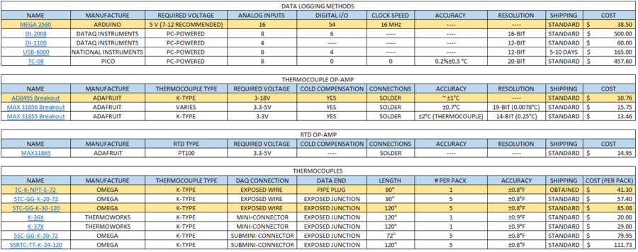
The data collection system had to inexpensive, accurate and simple to implement. We chose K-Type thermocouples as our sensors within the chamber. Thermocouples, while less accurate than RTD's, came in longer lengths, were less expensive and met our accuracy requirements. The thermocouple signal will be passed into operational amplifiers, these will boost the signal to be read by our central data collector. The operational amplifiers we chose come on a PCB with all connections easily identified and a calibration equation supplied. The thermocouple, operational amplifier, and signal headers will all be soldered together for strong connections. We also require a central data collector, to turn the signals from the op amps into readable data on a computor. We need to be able to set the microprocessor to take readings at discrete time steps, and since we are connected to a desktop computer we do not have to worry about memory. Below is the comparison table for the thermocouples, op amps, and DAQ's.
Final Design[edit | edit source]
This sections below will outline the final design decisions made for each component. We have also attached our system design files for clarity and information purposes.
Thermal Chamber[edit | edit source]
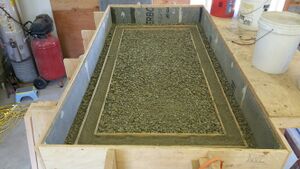
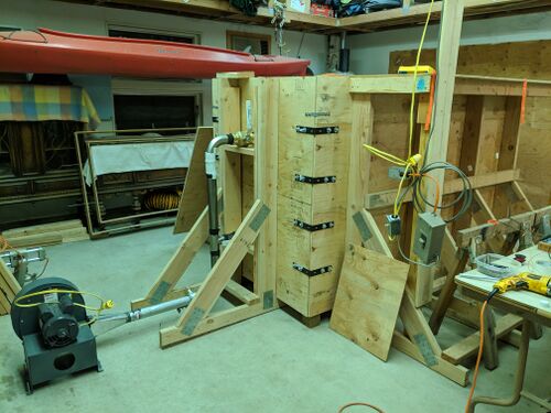
We decided to construct the chamber according to the designs created in the project learning phase. The number and distance of the supporting frame uprights was calculated using a maximum deflection method. We knew we did not want the sides to bow more than 1/8 of an inch, so using that as the maximum deflection we were able to calculate the maximum force allowed between each supporting upright. The results of these calculations are shown for clarity here. The chamber design proved to be simple to construct and strong enough to hold the required gravel. The layering of the chamber also proved to be simpler than we had anticipated. A jig was made that helped to evenly fill the gravel and keep the vertical layers the same distance from the sides all around.
In-Line Heater[edit | edit source]
As mentioned in the project learning section, we selected a 500 Watt air heater for the system. The heater can run on both 110 volt and 220 volt power. This allows for a "high heat" and "low heat" option. We will begin testing with the "low Heat" 110 volt connection. The heater will be controlled with a dimmer switch so that the air temperature can be controlled. This heater will be configured with the blower and piping system to deliver the air to the chamber. The OMEGA in line heater can be found here.
Air Blower[edit | edit source]
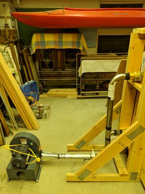
We chose a DAYTON 1 HP blower that runs on 240V single phase power. From the blower requirements calculations this air blower will supply 3 CFM of air through the chamber. The DAYTON blower can be found here. A converter was required to change the outlet dimension from a 3-1/2 X 4 inch square to a 2-3/8 inch circle. This adapter was donated by GROPP heating and cooling in Moscow, Idaho. The adapter was attached to the blower with high temperature calk and was attached to the heater by an adjustable sleeve. The blower and piping system are shown below.
Data Collection System[edit | edit source]
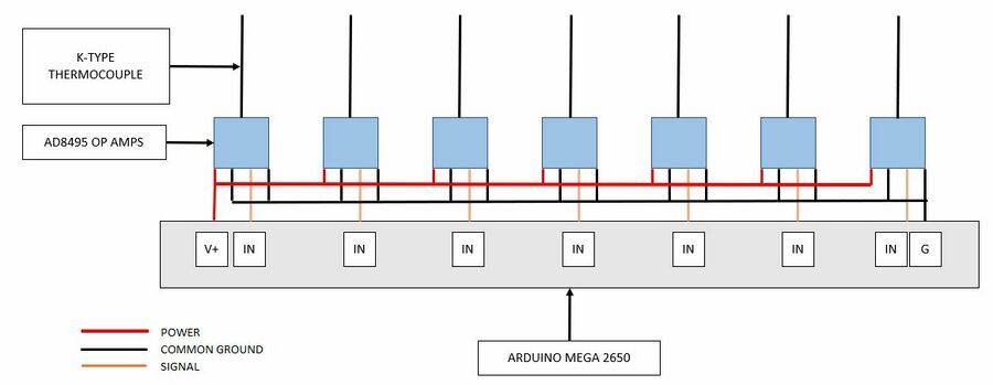
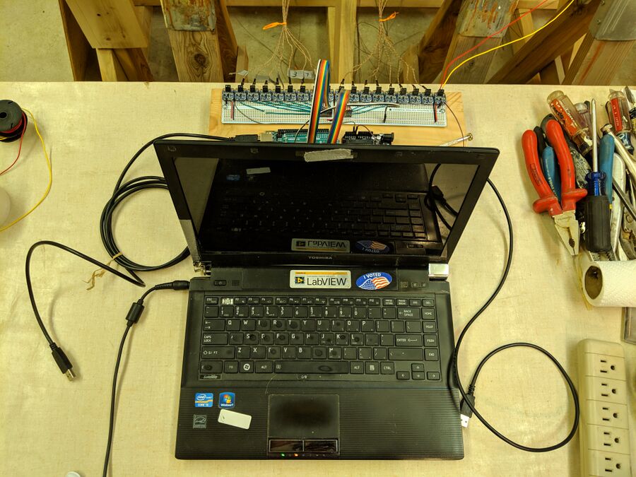
The data collection system will consist of three different components. For the thermocouples, we chose OMEGA k-type thermocouples. These thermocouples were long enough to meet our distance requirements and also met our accuracy requirements. We also selected two pipe plug thermocouples to collect data at the inlets and outlets of the chamber. For the op-amps, AD8495 amplifiers mounted to PCB were chosen. These met our accuracy and price requirments, and the PCB labeling made them easy to use. For the central DAQ, and ARDUINO MEGA 2560 was chosen. This board has 16 analog inputs and can write the signals to TXT files for later interpretation. A link to each device's datasheet is provided below.
- OMEGA K-type Thermocouples
- OMEGA K-type pipe plug thermocouples
- ADAFRUIT AD8495 Op-Amps
- ARDUINO MEGA 2560
