Development of a Low Cost Pyranometer
| Finished Product: The PV Matey | |
| Sponsors |
|
| Team Name | The Solar Sailors |
| Duration | 2020 - 2021 |
| Faculty Adviser |
|
| Client |
|
| Team Members |
|
The goal of the project is to design and test a prototype of a pyranometer, to be used by KiloWatts for Humanity to test solar irradiance of solar panels. A pyranometer is a device that measures solar irradiance in W/m^2 that shows how much sunlight that a solar panel is receiving. This is useful to know the solar panel energy output, as well as how showing how much sunlight an area gets to decide if the solar panel is in an optimal location, or if the solar panel needs to be cleaned or maintained. The prototype pyranometer will be compared to various pyranometers to test accuracy and viability.
Problem Definition[edit | edit source]
After installation, it is important to continue maintaining and monitoring the solar panel installations. To verify that solar panels are absorbing light energy properly, pyranometers are installed. Commercial pyranometers include extra features and average at $200. This organization is looking for an accurate and affordable alternative in the $20 range.
Our solution is to create a basic design that only measures solar irradiance. This involves learning about different pyranometer designs and sensors types currently being used and creating our own budget friendly design.
We will test and adjust our prototype against three calibrated commercial models until we can produce accurate results. Our final product will include a parts list, code, and instructions that are easy to follow so that our client can create pyranometers for future power stations.
Background[edit | edit source]
A pyranometer is a device that measures solar irradiance from sunlight. This is useful because it gives an accurate representation of how much light is hitting a solar panel. The value is measured in watts per squared meter to define how much light is hitting a section of the solar panel. Kilowatts for Humanity wants the pyranometer to measure the amount of sun light their solar panels are getting so that they can create more efficient way to generate energy and to make sure their solar panels are working properly.
Currently, Kilowatts for Humanity is using a $200 Apogee pyranometer that does more than they need it to. They have partnered with the University of Idaho to create a more affordable and effective pyranometer. The pyranometer that we create will be tested against the Apogee pyranometer, as well as another pyranometer from China. We hope to create a pyranometer that is just as accurate, if not more accurate than these pyranometers.
Client[edit | edit source]
The client for this project is the KiloWatts for Humanity organization. This non-profit installs solar powered stations that provide essentials such as refrigeration, laptop and phone charging, and offline servers. Some of these places include: Zambia, Kenya, Panama, and Cameroon. The host and co-founder of KW4H, Steve Szablya, is overseeing this project through the University of Idaho's Senior Design class.
Deliverables[edit | edit source]
The goal for this project is to create a low-cost pyranometer that can be used by the Kilowatts for Humanity organization. The final goal is for the prototype to cost around twenty dollars and to output a W/m^2 value. The pyranometer must be able to read the irradiance value of sunlight that can hit a solar panel. This value is then put into a 0-5V output This voltage output should then be put through a voltage-to-current converter to make the output a current output ranging from 0-20mA. This final output will go to a data logger and generate a graph by time that shows the amount of sunlight the solar panels are getting.
Specifications[edit | edit source]
The pyranometer prototype should have a 180 degree viewing angle, be protected from the environment, cost around $80-20, and accurately measure solar irradiance. It must also be able to be replicated by high school students and have a current output to reduce loss.
The data from our device must be accurate. Compared to calibrated pyranometers, our results need to have less than 15% error.
Design Considerations[edit | edit source]
The pyranometer attaches onto the solar panel, so something to consider is the mounting. There are a few choices for how to solve this. One way is to have a bottom mount and attach it next to the solar panel. Another way is to have side mounts to attach to the side of the solar panel. There are other options to consider before making a final decision.
The pyranometer is preferred to have a 180 degree field of view to be able to capture all sunlight on the plane. The sensor that we are using has a viewing angle of 150 degrees. We can accommodate for this by using two sensors. What must be considered is overlap and useless data from the sensors. Overlap can be solved in many ways. One such way is to include a screen divider to prevent overlap. Another way is to paint part of the sensor black, preventing a light reading from that side.
There are also environmental considerations, like sand or heat. The pyranometer must be able to withstand basic environmental issues before the prototype is sent out. The prototype will be testing inside of an environmental chamber before completion, and adjust based on the results to withstand heat, sand, rain, wind, and other environmental concerns.
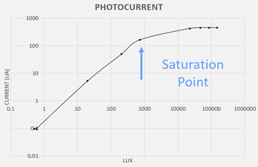
We also noticed in our testing that our sensor can only read a maximum of 1000 lux. Since sunlight is much more than this, we used a sheet of Teflon to attenuate the lux and to help prevent our phototransistor from oversaturating.
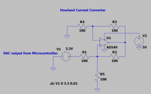
The last thing to consider is a voltage-to-current converter. The client wants us to be able to output the data as a current, rather than a voltage. Lukas Vermeulan designed the voltage-to-current converter shown below:
Project Learning[edit | edit source]
For this project, we needed to research into pyranometers. We looked into many different variations of pyranometers, including: Thermopile, Thermistor, Photodiode, and Phototransistor pyranometers. Through our research, we have found that phototransistors give the best viewing angle, while keeping the light that solar panels can receive. We did look into other options, and experimented with the thermistor solution, to give us a better understanding of our decision. However, we still decided that the phototransistor gave the best outcomes in terms of budget and data gathering.
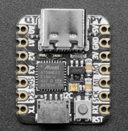
We are also using an Adafruit QT-PY as a microcontroller. This is used to take in the voltage outputted from the pyranometer, and scaling it to a 0-5V output. This is what will be observed in the data logger to represent solar irradiance. We chose this microcontroller because it is very small, which works best with our design. It also is cheaper to buy in bulk, with a 6-piece set coming out to $6.00 per microcontroller. This microcontroller also has a PWM output pin, which is perfect for our design. Below is a diagram of the microcontroller.
Final Design[edit | edit source]
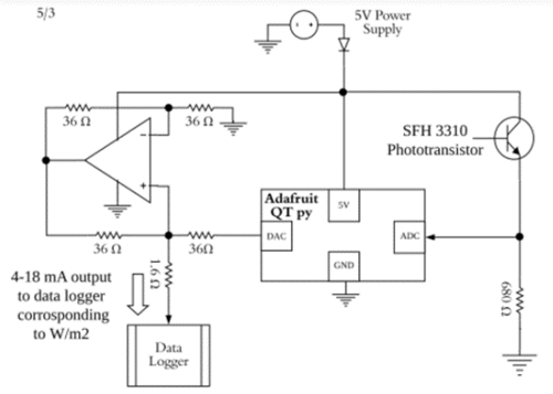
The design for our circuit involves the phototransistor, the microcontroller, a voltage-to-current converter, and various resistors. Our circuit takes in solar irradiance, and outputs a current signal between 4 and 18 mA. Below is an image of the final circuit design:
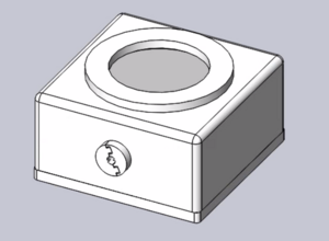
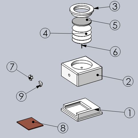
Our case involves the use of PETG 3D printing filament. Nickolas Borek designed the case and tested it to withstand various problems, such as dropping and rain. The final product design involves four sheets of Teflon to attenuate the light, an acrylic disk to protect the components while still allowing for light, and all of the components of our circuit. The final design of our product is given below:
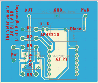
Instead of using a basic breadboard for our circuit, we decided to go with a PCB that was printed at the University of Idaho. This PCB is a copper based board that has all of the connections through the board. All that is required is to put the components in the holes, and solder them to ensure a proper connection. Below is an image of the PCB.
Validation[edit | edit source]
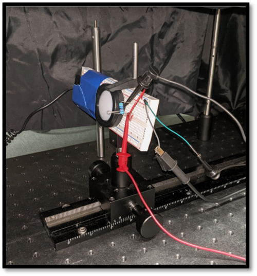
Firstly, we performed a sensor test. The datasheet for the sensor had limited knowledge in terms of the output of the sensor. To get a better idea of how our sensor worked, we wanted to perform a test to find the voltage output in terms of lux. The datasheet had this graph, but it only went up to 1000 lux, and we wanted to see what happened past this point. We found that, after 1000 lux, the sensor gets saturated and stops being a linear curve. This was the basis for the Teflon filter below. We had to find a way to avoid the non-linear region of our sensor so that data was accurate. Below is an image of the sensor test.
 |
 |
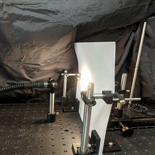
Next, we performed a few different tests to gauge the accuracy of our device. The first test we conducted was for the Teflon filter. We put an adjustable light source in front of the Teflon sheet, and measured the lux through this filter. Our goal was to find out how much light our filter attenuated. Through our testing, we found that the Teflon sheet attenuated 73.8% of incoming light. Using this attenuation value, and the fact that the Sun has a maximum value of 120,000 lux, we found that our device would need four sheets to attenuate the light down below the sensor threshold value of 1000 lux. Below is an image of the Teflon test.
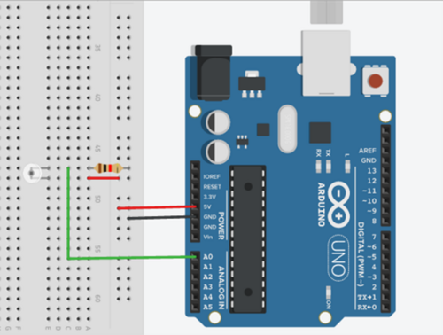
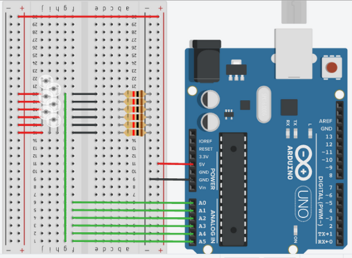
A virtual test that was performed was TinkerCAD Simulations. We used these tests to get a simulated response out of the phototransistor. While the specs of the devices weren't perfect, they were very close. These simulations were used to make sure that everything would work how we wanted it to, so that we could order the parts and have confidence that everything would work. Below are the images of the TinkerCAD simulations.
 |
 |
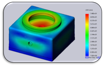
Another virtual test that we performed was a drop test. We wanted to make sure that our device could be dropped from a one story building and survive. The image below shows the stress on the box as it hits concrete. The case will not break, but it is possible for the sensor plug on the top to get lose and come off of the case. Overall, we are satisfied with this stress test result.
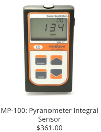
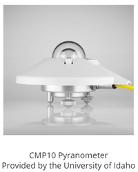
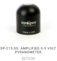
Unfortunately, we were not able to use the pyranometers given to us from the organization KW4H. It required components that we did not have access to. We were also not able to use the school's pyranometer as it required access to a data logger, which we did not have. However, we were still able to use the handheld pyranometer- the MP100 handheld pyranometer- to test and calibrate our sensor. This pyranometer was compared with the values that we received from sunlight, and then further used to calibrate our sensor to give us more accurate readings from the Sun. All three pyranometers are shown below, but we were only able to utilize the first one.
 |
 |
 |
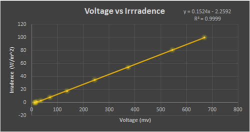
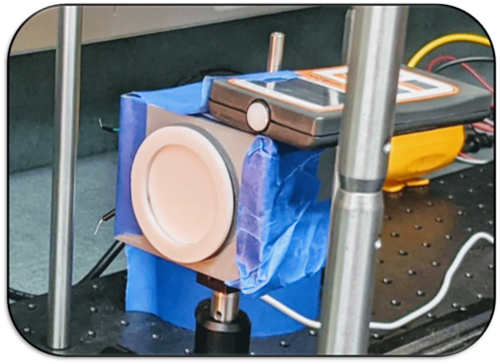
The next test that we performed was a calibration test. To calibrate the device, we set our prototype next to the hand-held MP100 pyranometer to compare outputs. Using an adjustable light source, we found a linear graph of voltage vs. irradiance, and used the slope equation to calibrate our prototype. The calibration curve (left) and test setup (right) can be found below.
 |
 |
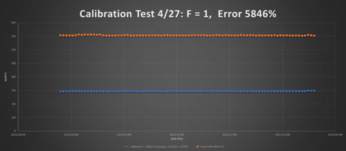
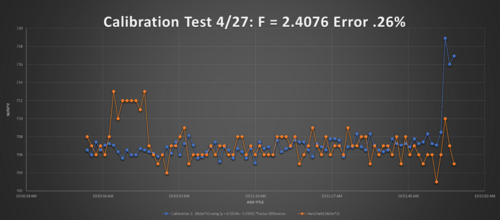
The last test that we performed was a field test. We compared the hand-held MP100 pyranometer to our calibrated prototype to see the difference in values. The graphs (found below) are in time vs W/m^2. The blue line is our calibrated prototype, whereas the orange line is the MP100 pyranometer. The first graph appears to be very far off. However, there is a calibration factor that needs to be taken into account. Through our equations, we found that our calibration factor was 2.4076, which made the graph reduce its error to 0.26%. The images below are the calibration test without the factor (left image) and the test with the factor (right image).
 |
 |
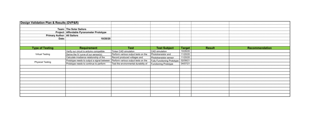
Below is an image of our Design Validation Plan that shows our plans for virtual and physical testing planned in the future.
Team Members[edit | edit source]
The Solar Sailors are a group of University of Idaho undergraduates who are working with KiloWatts for Humanity to create a low-cost pyranometer from 2020 to 2021. The team consists of Lukas Vermeulen (EE), Adriana Oliveira (EE), Brady Jerome (EE), and Nickolas Borek (ME). As part of their Senior year, they have been assigned to tackle this task together and to learn valuable industrial skills throughout the year.
|
|
|
|
Additional Documentation[edit | edit source]
Project Schedule
Project Budget
File:Approved Pyranometer Budget.pdf
Meeting Minutes
File:Meeting Minutes 09-08-20.pdf
File:Meeting Minutes 09-09-20.pdf
File:Meeting Minutes 09-14-20.pdf
File:Meeting Minutes 09-16-20.pdf
File:Meeting Minutes 09-21-20.pdf
File:Meeting Minutes 09-23-20.pdf
File:Meeting Minutes 09-28-20.pdf
File:Meeting Minutes 09-30-20.pdf
File:Meeting Minutes 10-05-20.pdf
File:Meeting Minutes 10-07-20.pdf
File:Meeting Minutes 10-19-20.pdf
File:Meeting Minutes 10-21-20.pdf
File:Meeting Minutes 10-26-20.pdf
File:Meeting Minutes 10-28-20.pdf
File:Meeting Minutes 11-02-20.pdf
File:Meeting Minutes 11-16-20.pdf
File:Meeting Minutes 11-18-20.pdf
File:Meeting Minutes 11-27-20.pdf
File:Meeting Minutes 01-29-21.pdf
File:Meeting Minutes 2-12-2021.pdf
File:Meeting Minutes 2-17-2021.pdf
File:Meeting Minutes 2-19-2021.pdf
File:Meeting Minutes 03-03-2021.pdf
File:Meeting Minutes 03-05-2021.pdf
File:Meeting Minutes 03-10-2021.pdf
File:Meeting Minutes 03-12-2021.pdf
File:Meeting Minutes 03-24-2021.pdf
File:Meeting Minutes 03-26-2021.pdf
File:Meeting Minutes 04-07-2021.pdf
File:Meeting Minutes 04-09-2021.pdf
File:Meeting Minutes 04-14-2021.pdf
Presentations
File:Presentation1.pdf
File:Concept Review Fall 2020.pdf
File:Design Release Review.pdf
File:FINAL SLIDESHOW.pdf
Low-Cost Pyranometer Poster
Bill Of Materials
FMEA
Design Report
User Manual
File:The Solar Sailors User Manual.pdf
PCB File Download
