FHSAE Voltz N Boltz
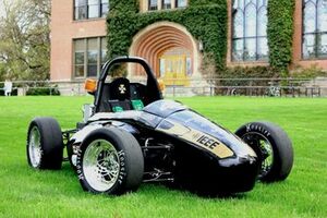
| Formula Hybrid Vehicle picture from 2012.
(photo courtesy of ___________) | |
| Sponsors | |
| Team Name | Voltz N' Boltz (FHSAE) |
| Duration | Fall 2013 - Spring 2014 |
| Faculty Advisers | |
| Mentor | |
| Students |
|
The Vandal Hybrid Racing Team is a non-profit organization which advances the education of future engineers by designing and building a vehicle to compete in the annual Formula Hybrid competitions. The mission of the Vandal Hybrid Racing Team is to build the best Formula Hybrid vehicle possible using our acquired engineering and real world skills while having a good time. The Vandal Hybrid Racing Team is a great way for students to gain appreciation for the hands on side of engineering. Many skills used to build the formula hybrid vehicle are not taught in the class, but gained through trial and error along with plenty of practice. Because of the vast range of skills students learn while being a team member, the project produces very well rounded engineers with an appreciable understanding of how to apply engineering principles to every day challenges.
Sub-System Redesigns
| SUB-SYSTEM | DESIGN DEVELOPMENT | DESIGN IMPLEMENTATION |
|---|---|---|
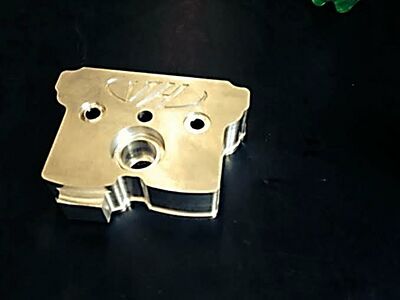
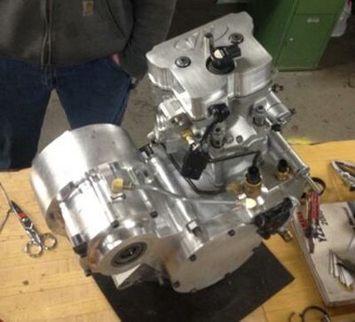
| VALVE COVER | ISSUE: At the beginning of the year we were only equipped with one valve cover and two engines (one for the dyno and one on the car). This was inconvenient because of the time that it took to switch them out between testing on the dyno and physical testing of the car.
SOLUTION:
|
|
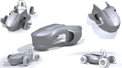
| BODY | ISSUE:Need a new lightweight body design. We need to figure out how to mold it, how to scale it to fit the vehicle, and make sure the body shape will fit correctly around the frame and components.
SOLUTION:
|
|
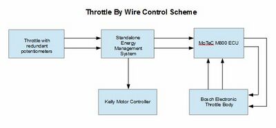
| DRIVE BY WIRE | ISSUE: The throttle body is actuated by old worn out cable design. We need to update drive by wire for throttle body system.
SOLUTION:
|
|
| THROTTLE BODY | ISSUE: update throttle body for electronic drive by wire.
SOLUTION: |
|
| SUSPENSION | ISSUE: Current suspension design is outdated compared to other teams using composite suspension materials.
SOLUTION: |
|
| TRACTIVE SYSTEM MEASURING POINT (TSMP) | ISSUE: Old design doesn't incorporate Ground Low Voltage (GLV) measuring points.
SOLUTION: |
|
| APEX JOINT | ISSUE: In need of replacement in order to reduce steering wheel slop.
SOLUTION:
|
|
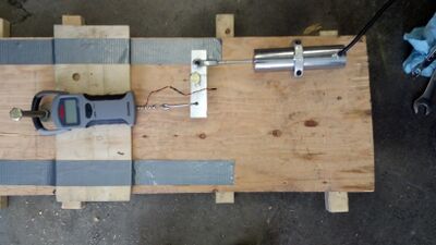
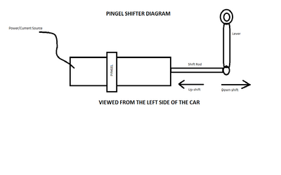
| PINGEL SHIFTER | ISSUE: Pingel shifter lacks capability to downshift, and sometimes has problems upshifting too.
SOLUTION:
|
|
| STAGING CLUTCH | ISSUE: Need new staging clutch to get more torque and higher RPM's when accelerating from rest. This issue may arise from our Rekluse clutch that was used as the replacement for our manual clutch. We can't just buy a new manual clutch because he YZ250F engine is custom machined so it wouldn't fit properly.
SOLUTION:
|
|
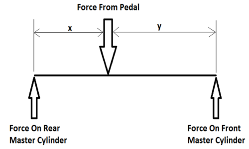
| BRAKES | ISSUE: Brakes severely drag/lock up when hot and the normal brake drag increases rolling resistance, low pressure brake lines were not protected lines (need to be braided metal as stated by rules), a single hydraulic reservoir was used to supply the front and rear master cylinders with hydraulic fluid and is inadequate, and brake over travel switch only momentarily shuts down the vehicle when it needs to be permanently shut down in the event that the brake pedal travels too far (ex: hydraulic leak).
SOLUTION:
|
|
| ENGINE MANAGEMENT | ISSUE: Engine needs to be tuned and maintained at an optimal level.
Rules:
Key Components:
SOLUTION: |
|
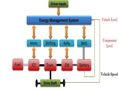
| ENERGY MANAGEMENT | ISSUE: no effective coordination between the electric motor and the engine. User must choose which mode (electric, Internal combustion, or Hybvrid) to run in which is extremely inefficient and does not utilize the system to it's full potential.
SOLUTION:
|
|
| DATA ACQUISITION | ISSUE: on-board data collection is needed to support future development.
SOLUTION:
|
|
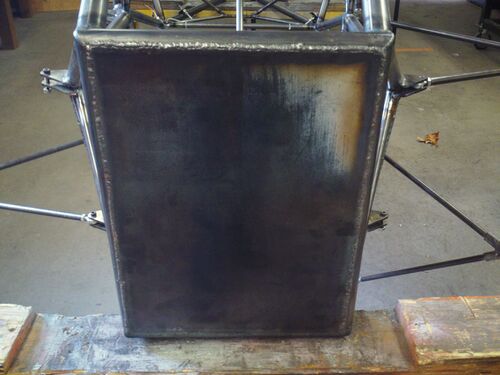
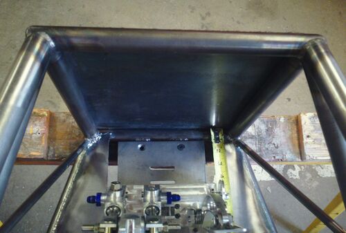
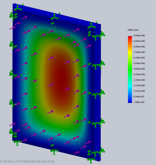
| FIREWALL | ISSUE: Hybrid rules changed, we have to make sure the firewall is sealed and in compliance with any other rules.
SOLUTION: |
|
Competition Design Analysis
Structural Equivalency Report
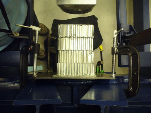
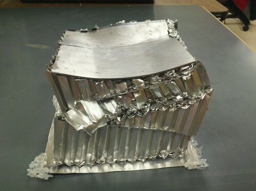
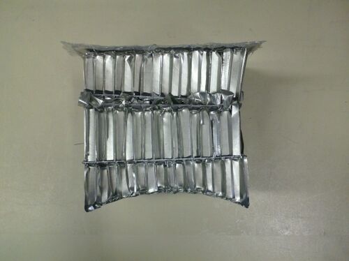
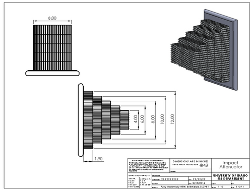
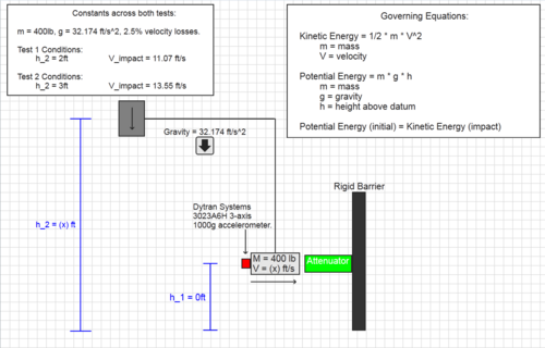
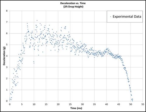
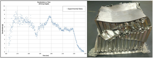
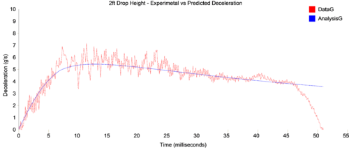
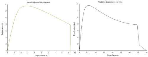
Impact Attenuator Report
Design Report
High Voltage DFMEA
Marketing Presentation
Testing
Local Track Layout
Acceleration
Autocross
Engine Testing
Motor Testing
Team Profile
| TEAM MEMBER | BIOGRAPHY | SUB-SYSTEM ASSIGNMENTS & DUTIES |
|---|---|---|
| Jordan Anderson, M.E. | I am a senior mechanical engineering student at the University of Idaho. I grew up in northeast Washington playing sports. I have always enjoyed motorsport and have been a member of the formula hybrid team for the last three years. My responsibilities have been extremely various from cutting out firewall closeouts, to designing an engine management wiring harness to design of a throttle by wire system. I will graduate with a B.S.M.E. in May of 2014. | Throttle By Wire & Throttle Body
Engine Management |
| Jonathan Andring, M.E. | I am a senior mechanical engineering student at the University of Idaho. I grew up most of my life in northern Idaho and enjoy many outdoor activities including, skiing, hunting, fishing, snowmobiling, and ATV riding. I also enjoy engine rebuilding and tinkering on various mechanical systems. When I graduated from high school, I went to North Idaho College for the Welding Technology program. After graduating from this program, I went to work for Diedrich Manufacturing, a manufacturer of high end coffee roasters. My work at Diedrich Manufacturing included fabricating/welding tubular and sheet metals parts, many of which were labor intensive and detailed. I also worked on many new designs/prototypes. After about three and a half years, I came to the conclusion that I wanted to go back to school for mechanical engineering. Now, four and a half years later, I am on the hybrid formula car SAE design team, and will be graduating in May of 2014 with my B.S.M.E. | Brake System & Pingel Shifter
Chief Engineer |
| Derek Arrotta, M.E. | I grew up in Spokane, WA and have done most of my higher education in Idaho. I've continuously been on the deans list and honor roll the past two years at the University of Idaho, passed the FE exam, and currently have a 3.52 GPA. I'm a huge fan of music, I play the guitar, love to play basketball and soccer, rock climb, and hike in my free time. So far I've been interested in creative design (Solidworks and CATIA) and the dynamics of project management. Although career-wise I am open to all forms of engineering and am eager to learn more. | Engine Management
Wiki Manager, Rules and Safety Officer, ESAC funding, CATIA Manager, and I helped with body, firewall, and early Pingel Shifter design. |
| Amos Bartlow, E.E. | I grew up in Nampa, ID where my love for engines and vehicles came about by riding dirtbikes, snowmobiles, and various other recreational vehicles. If it has a throttle, goes fast, and burns fossil fuels, count me in. I am a senior in electrical engineering with an emphasis in high frequency circuits, and micro-controllers. I have had the opportunity to be a member and am currently a captain on the SAE clean snowmobile challenge team, which is unique as an electrical engineer. I really enjoy combining my love of vehicles and my fascination with electronics in the FHASE and CSC teams. As an Air Force ROTC cadet, upon graduation, I will commission as an officer in the Air Force and go to Pilot Training in Texas, where I look forward to taking my passion for vehicles and electronics to the skies. | Energy Management, Low Voltage Controls, High Voltage Tractive System |
| Adam Bunch, M.E. | I am a Mechanical Engineer at the University of Idaho and will be graduating May 2014. I chose engineering because of my passion for racing and always trying to achieve top performance on whatever I was racing. I have been racing since I was of age to do so and because of that I joined the FHSAE team for senior design. I am currently assigned to the frame, impact int. and a redesign of a staging clutch for the car. Aside from engineering I am a member of Sigma Alpha Epsilon fraternity and ran track for the University for two years. | Frame, Impact Attenuator |
| Ignacio Lopez, M.E. | A part of society of hispanic professional engineers, dean's list. | Body, Ergonomics, Future Re-gen, Firewall |
| Nathan Peterson, M.E. | A part of SAE, theta chi fraternity, and resonate church. Achievements include dean's list (fall 2013 and spring 2012) and center for advanced energy studies (CASE) scholar. | Suspension, Tractive System Measurement Point (TSMP), Apex Joint |
| Artemio Ambriz, V.T.D. | I was born and raised in the small town of Rupert Idaho. I have always been fascinated with design and the virtual world. I knew I wanted to pursue higher education doing what I loved to do, so I decided to major in Virtual Technology and Design at the University of Idaho. I self-taught myself 3d Studio Max which is a 3d computer graphics program when I was a sophomore in high school. Vehicle Design and Racing are my main interests, which is why I wanted to be a part of FHSAE. I am also a member of Aerospace and Augmented Reality senior capstone group for my major. I will be graduating May of 2014 with a B.S in Virtual Technology and Design. | Body Design
Designed the new body shape |
Document Archive
Gant Chart
Team Meetings
Formula Hybrid Competition
Research Papers and Info
- Weight Reduction Techniques of FHSAE
- Design and Math Modeling FHSAE Drivetrain
- Opportunities on FHSAE for Ultra Capacitors
- UTC Project Information
- Intake Design for Max Performance
- Fuel Injection and Intake/Exhaust Sizing of a YZ250F Engine
- Italian Powertain Thesis
- Improved Multi-Objective Genetic Algorithm for Geometric Optimization of FHSAE Vehicle Suspension
- The effect of Intake Manifold Runners Length on the Volumetric Efficiency by 3-D CFD Model
- Hybrid-Electric Planetary Drivetrain Design for Automotive Applications
- Design, Construction, and Validation Testing of a Hybrid Vehicle
- Real-time Optimized Performance Control of a Formula Society of Automotive Engineers Hybrid Vehicle
- Electronic Fuel Injection System Design for Single Cylinder Motorsports Applications
- Electric Propulsion Subsystem for a Parallel-Drive Formula Hybrid Vehicle
- Racecar: Searching for the Limit in Formula SAE
- SAE Vehicle Powertrain Calibration Engineering Telephone Webcast
Engine User Manuals
- Yamaha WWR250R Service Manual
- YZ250 Parts Manual
- WR250X User Manual
- WR250RX(C) & WR250XX(C) Yamaha Service Manual
