FINGER 2.0 Thumb Rehabilitation Mechanical Design
| [[File:|300px|center|alt=]] | |
| Sponsors | The National Center for Medical Rehabilitation Research at the National Institute of Child Health and Human Development |
| Team Name | Thumb Wrestlers |
| Duration | 2020 - 2021 |
| Faculty Adviser | Dr. Joel Perry |
| Mentor |
|
| Client | Dr. Eric Wolbrecht
|
| Team Members |
|
The goal of the project is to complete and refine the mechanical design of the added 5-bar thumb module system to allow the new FINGER 2.0 rehabilitation robot to be used for both left handed and right handed finger dexterity and movement for post stroke victims.
Problem Definition[edit | edit source]
-Mitigate the joint slop and looseness to allow the FINGER 2.0 to be as effective as possible in making accurate movement assists to help regain finger dexterity.
-Design a new baseplate and left sided thumb module to allow FINGER 2.0 to be used for both left and right hand impaired stroke victim rehabilitation.
-Check final form, fit, and function of FINGER 2.0 to ensure comfortability and ease of use for both rehabilitation patients, as well as medical professionals who will be operating the robot.
Background[edit | edit source]
Over 800,000 people suffer from a stroke in the United States every year alone. Of the survivors, over 2/3 experience long-term impairment of the affected upper-extremity. The use of robotic rehabilitation can automate the repetitive and difficult process of conventional physical therapy that comes after a patient has experienced a stroke. Robotic therapy can also serve as a scientific instrument for quantifying the recovery process and provide insight that is often unavailable with conventional physical therapy.
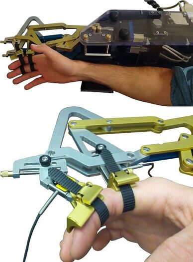
The original FINGER 1.0 sought to maximize controller fidelity and minimize mechanical impedance. It did so by having only one degree-of-freedom, high controller fidelity, and low friction joints and bearings. It only assisted with middle and pointer finger rehabilitation by utilizing a 8-bar mechanism and having the user make a common grasping motion. FIGNER 1.0 controlled the orientation and position of the middle phalanx of each finger.
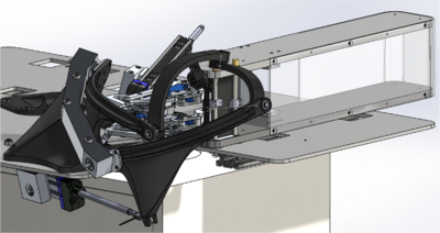
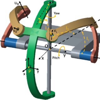
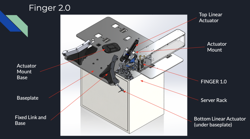
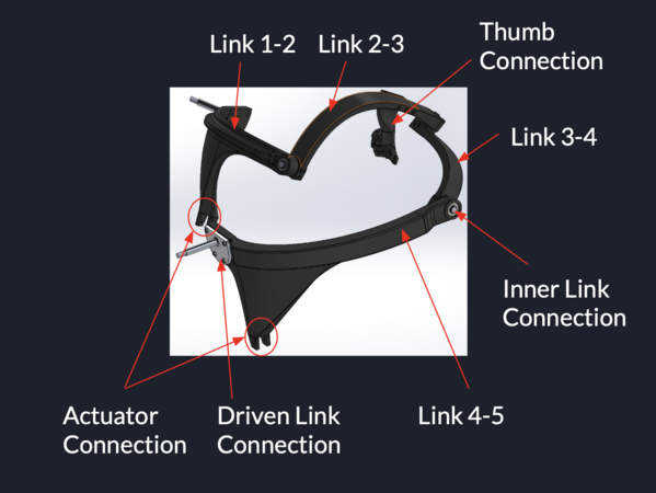
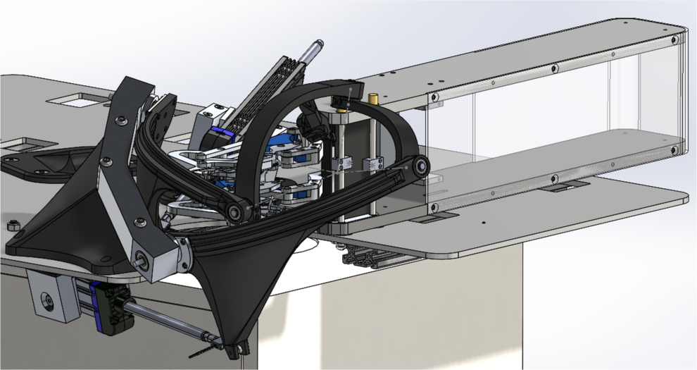
FINGER 2.0 was designed before being assigned to our group. It differs from FINGER 1.0 because it also incorporates the thumb in the rehabilitation process. It consists of a spherical 5-bar mechanism that translates a normally 2 dimensional path to 3 dimensional space. The thumb module has 5 links, all attached at both ends to other links. Two actuators allow the system to take input from the user and manipulate that data into a position to help the patient regain their finger dexterity and natural grasping movements. The original mechanism is very well designed, but has some issues that our team has been tasked with redesigning.
Deliverables[edit | edit source]
For this project, our deliverables will be two prototypes of the FINGER 2.0 robot. Pre-existing geometry and structure were provided at the start of the project. The goal of prototypes one and two are to increase the overall rigidity and precision of the mechanism. Both prototypes will be capable of operation by both right and left-handed users.
Prototype one will focus on the joints between links to simultaneously reduce deflection and friction. This will be done by combining machined connections with 3D printed links to create precise geometry. Prototype two will focus on the links themselves to reduce the flex of individual members in the system. This will be done by combining different materials, print in-fills, and link geometries to minimize the flex of the links while operated.
Design Considerations[edit | edit source]
Joint Connections[edit | edit source]
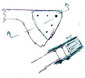
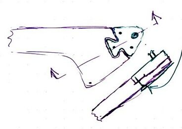
For the joint designs to combine machining and 3D printing, several different options were considered. The first design was the “End Mount”. This design involved setting a threaded insert into the link perpendicular to the joint and bolting the machined block onto the narrow “end” face of the link. This idea had the benefit of being easily manufactured as one large chunk but came with the negative of having a potential failure mode where the threaded inserts ripped free of the link. The second design was the “Dovetail” which pulled from a similar design in woodworking. The shaft would be machined with a flange at the base with an angled tongue that would fit into a matching indent on the link. The flange would then be used to bolt to the link parallel to the shaft. This design was more difficult to machine but would help locate and lock the flange in place once mounted. The third design was the “Sandwich” joint. Similar to the dovetail, this design used a shaft with a base flange to connect to the link. Unlike the dovetail, the shaft would run through the link and the flange would mount on the inside of the link. On the outside of the link, a matching plate would be used as the clamping surface for the bolts. This design relieved much of the compression stress on the link from the mounting bolts but also required more pieces to provide support. The “Face Mount” design was very similar to the dovetail design, differing in the absence of the tongue. This design was easier to manufacture but did not lock the shaft to the link as securely.
Project Learning[edit | edit source]
File:Water jet vs router table.pdf
File:ProjectLearning-Tolerances.pdf
File:ProjectLearning-Fillet.pdf
File:Project Learning Shaft Hole Tolerances.pdf
File:Bearing Preload Project Learning.pdf
Final Designs[edit | edit source]
System Overview[edit | edit source]
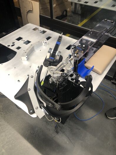
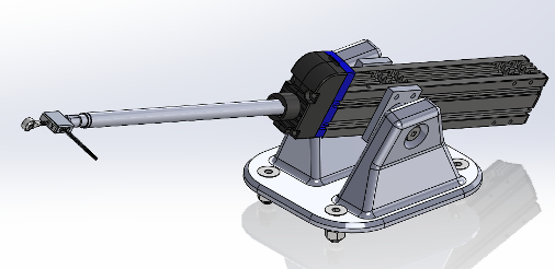
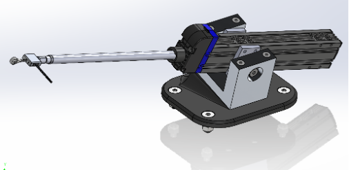
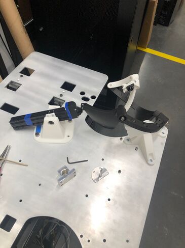
Below is a basic overview of parts worked on to show general location and assembly of the FINGER 2.0 robot.
Driven Link Connections[edit | edit source]
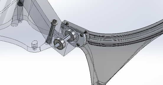
One of the two main problems in the 5-bar mechanism was the slop within the joints. The previous design utilized shoulder bolts as an axle, with the mounting nut embedded within the 3-D printed link. This allowed for a great deal of play, both between the bearing and the shoulder bolt, as well as between the shoulder bolt, nut and link at the imperfect connection. The goal of the joint redesign was to eliminate the perceptible slop in the joint, with a side consideration of reusing as much hardware already used in the original design.
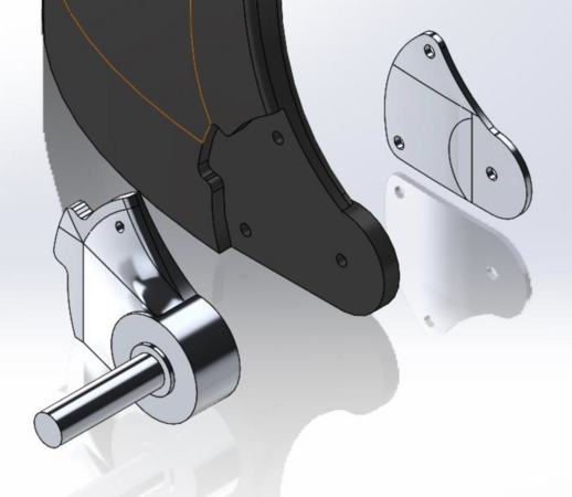
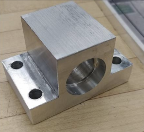
The face-mount design addresses both areas of joint slop to provide a solution. To get a high degree of precision and low tolerance between the bearings and the shaft, the shaft was precision-machined to match the bearings. The shaft then needed to bolt onto the printed link. To reduce any possible moments on the connection between the shaft and link, due to the potential issue of the bolts pulling through the link, a wider shaft base was implemented. The “D” shape of the face is to match the bottom surface of the links. Matching the bottom surface of the links made for a simpler print, reducing unnecessary additional print supports and orientation complications.
Actuator Mounts[edit | edit source]
A less central problem that was resolved was the actuator mounts and the ability to swap the mounts from side to side easily. For the design, only two actuators are used, needing to be swapped from side to side for use on different sides of the body. The original design necessitated the removal of the bolts that functioned as the axle for the actuators. Getting the bolts to thread back into the nuts after transitioning sides proved to be somewhat irritating and more time-consuming than desired, as did the awkward angle required to reach one of the bolts.
To make the transition simpler, the actuator mount was separated into two sections: an upper machined portion and a lower 3-D printed portion. The lower portion was printed for ease of manufacturing due to the unconventional angle of the actuators, while the upper portion was machined for maximum precision in the connection between the two section. To transition from side to side, the four bolts that run through the machined portion are undone, then fastened back down into the angled base on the other side.
Inner Joint Connections[edit | edit source]
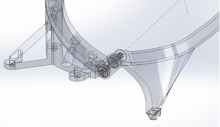
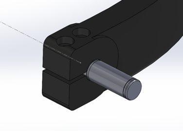
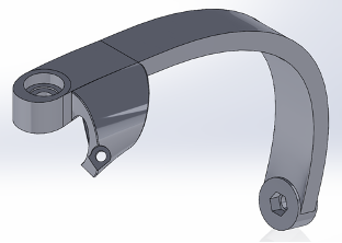
The inner joints needed to be redesigned to remove the play from joints themselves. Originally the links used a shoulder bolt that went through two bearings and bolted onto the other side of a link. This caused quite a bit of play because the shoulder bolts did not fit the bearings perfectly, and the joint could not be tightened enough to remove that play. The new design needed to be sleek and rigid, so that the deflection at the thumb location was minimized. A few different designs were talked about including a dove tail slot, face mount and a clamping link end. The design the team chose for the inner joints was the clamping link end. This design features a custom-made shaft and complete redesign of one of the link ends.
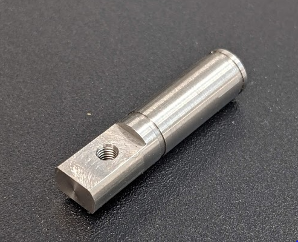
The custom shaft contains a few distinct design features that let it shine in the final build of the robot. The first being two groves, one at either end, of the shaft that house retaining rings to compress onto the bearings and hold the shaft in place. The team utilized 0.20mm shims in order to create a preload on the bearings to remove any play that the bearings themselves introduced into the system. At one end of the shaft, the circular profile was machined down to become an oblong rectangle with a hole drilled directly through the center of the rectangle. The change in profile was useful for a few reasons. It initially made it easier to drill the hole into shaft because it gave a flat side for the drill bit to rest on. It also served as a piece of geometry that would resist turning in the clamping link end.
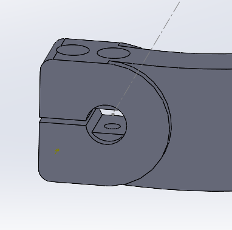
One of the link ends was redesigned to be a clamp that would clamp onto the oblong profile of the custom shaft. The key features are the shape of the hole that the shaft fits into and the multiple bolt holes that go through the link end. The hole for the shaft was a negative of profile of the shaft but sized up slightly because of the shrinkage of 3D printed materials. The shape itself was used to counteract any twisting that the shaft would be able to do if it were completely round. There were two bolt holes on the link end as well. One was to allow a bolt to go directly through the shaft to assure that there was a connection between the shaft and the link end. The other hole passed through a slit in the link end that when tightened down it would close the slit and apply pressure onto the link to act as if it were gripping onto it.
Thumb Connection[edit | edit source]
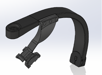
The way that the thumb piece connected to the link needed to be redesigned for a few different reasons. One of the main reasons was to be able to adjust the thumb piece to accommodate different hand sizes. This part of the design was completed through making different sizes of the connection piece. There is a single dimension in the CAD file that when adjusted it makes a piece in the part shorter or longer which moves the thumb in or out from the center. With this design, the shorter the piece is, the larger the hand that fits comfortably in it. Another big reason to redesign this part was to reduce the size of the connecting piece to allow better view of the thumb and hand by the patient and the technician. The original design had a bulky wave that came almost over the patient’s hand to connect to the thumb piece, and this was very disrupting to the user as they could not see if their thumb was moving as they thought it was. The redesigned connection is located forwards on the link and has a slimmer profile to avoid being in the way of the user’s view. The connection point also uses a three-bolt pattern that resists the rotation of the connection, which made it a more secure part as well.
Baseplate[edit | edit source]
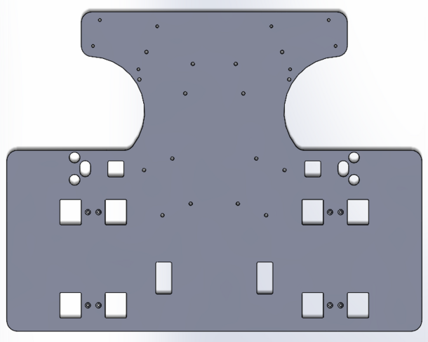
Early on in the design process, it was decided amongst the group that the baseplate would be a mirror of the previous FINGER 1.0 baseplate. Its construction would consist of .250" 7075 aluminum plate that would be sourced from a local water jetting company in Lewiston. The new baseplate would have an extra 3" in the center to spread the entire server rack, as well as extra holes at both ends for wiring force sensors. The most limiting factor on the baseplate was water jet sizing. Originally, the WSU water jet was going to be used and it was fairly small. The baseplate would have to be made in two separate pieces which would have been less desirable due to the 80/20 bar mounting system to attach it to the server rack. Gateway Materials in Lewiston had a much larger water jet that was able to accommodate the entire part. The small holes that attach the baseplate to the 80/20 require countersinks and it was not feasible to be cut on the water jet due to the small hole diameter. Once finished, the baseplate was brought back to the University of Idaho and countersinks were cut in the shop using the drill press.
Fixed Link[edit | edit source]
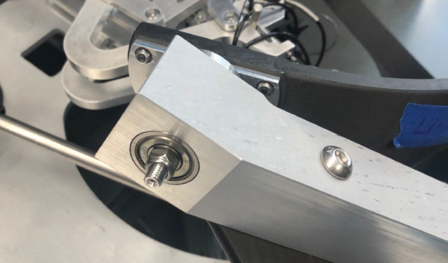
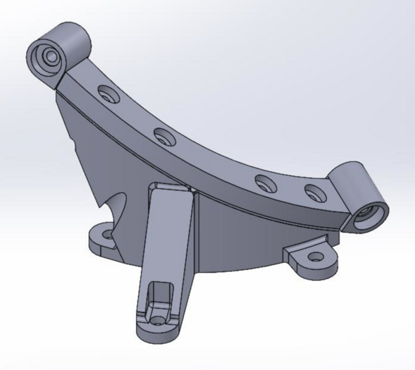
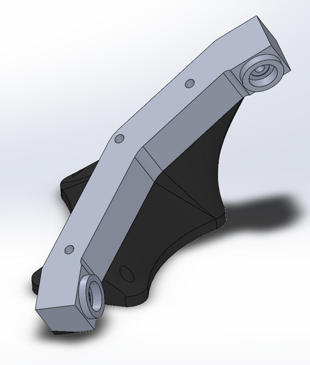
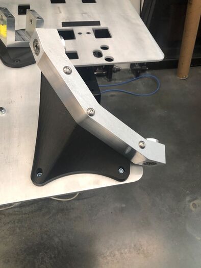
During construction of the previous FINGER 2.0 prototype, it became evident that the previous fixed link design was inadequate in some areas. Due to the orientation in which the top link had to be printed, the bearing bores in each end were not exact which caused a loose fit for the bearings and play in the joints. So, one of the assigned tasks was to have the fixed link machined and attached to a new redesigned base. Original efforts were made to make the previous link square on the ends. Due to the nature in which the part was originally made in SolidWorks, this idea was quickly scrapped and a decision was made to have the link made of a 1.5" 7075 aluminum stock and bolt down to a new base that would be attached to the baseplate. The reason for the tall height was for the link to be symmetric in the vertical axis to allow for switching from left to right if needed. The new fixed link also has bosses cut around its connection to the driven link connections for clearance of the nuts. The fixed link is attached to its new lofted base using heat set inserts the team found on McMaster Carr. The base was also edited to adhere to the links new compound angle design. Long curves on the base allow for a decrease in stress concentration factors and overall more aesthetically pleasing design.
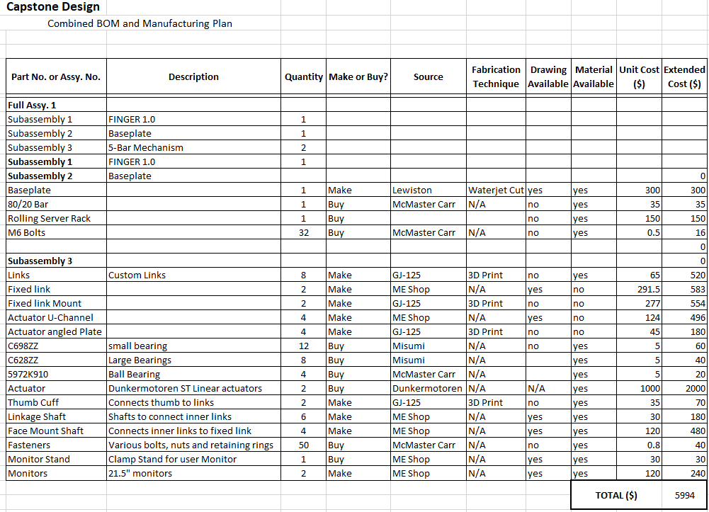
Bill of Materials[edit | edit source]
Validation[edit | edit source]
Design Validation is a big component of any project. For the FINGER 2.0, our design validation is broken into two main component tests: the base-plate and the link connections. For the base-plate, our design validation is a combination of a solidwork's mock-up, where all mounts and parts will be placed on the base-plate to test if everything needed will fit, and a post production weight test, where we will be leaning on the free end of the plate to determine if the deflection is enough to warrant an addition of more support 80/20 bars.
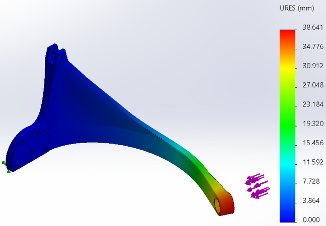
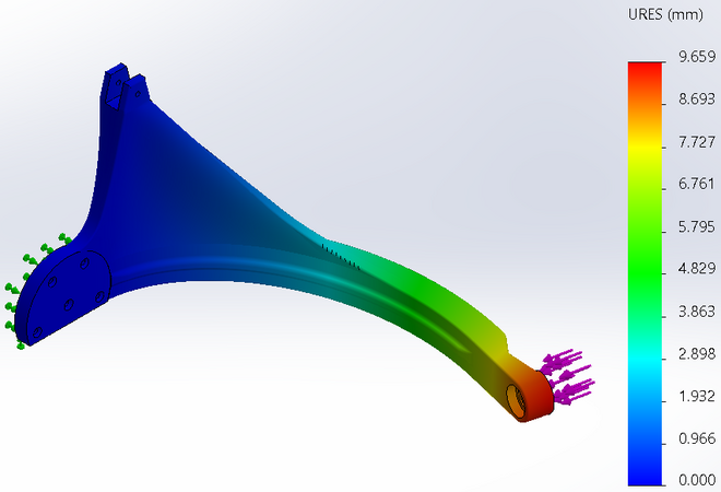
The validation for the link connections came from a custom testing jig. The jig is machined out of aluminum and designed to have the same spacing and size of bearings that are on the actual links of the FINGER 2.0. We then took our designs and put them to the test on the rigid fixture, where we attached the link and our custom ends to test deflection and how rigid the connection to the joint is. Another source of validation for the links themselves came from using the FEA features in SolidWorks. A flat plane on the end of the driven links was fixed and a force was applied to the other side. This allowed us to compare previous designs with new ones to quantify the decrease in link deflection.
Future Work[edit | edit source]
On the idea of moving the project forward, the end goal is to have a fully functioning prototype to send to the University of California Irvine in the not-so-distant future. The current model could be replicated to the left side and sent on its way, but our team ran into printing material limitations that need to be taken into account. With virtually all of the slop and play taken out of the joint connections, the only areas of design to change would be in the actual geometry and shape of the links themselves. Our team was able to decrease joint deflection by adding a “tee” shape to links 1-2 and 4-5, but with the added cost of extra weight. There were many ambitious designs that were suggested, but our team was simply too limited on time when the issue was noticed.
The capstone team cannot speak for the controls side of the project, but the mechanical aspects of FINGER 2.0 are nearly complete. There are features that were not included such as a physical hard stop that would be attached to the links to prevent the linear actuator rods from falling out, but the team captured that element with neoprene washers at the end of the rods. Another aspect that our team failed to capture was the adjustable wrist piece, but it was decided to be out of scope for the project. An area that could use some refinement would be the actuator switching blocks. The original idea was to use a toggle clamp to move the actuators from left to right. It proved to be rather involved and would have taken considerably more time, so our team stuck with the four-bolt design.
As far as budget and duration for the future work of the FINGER 2.0 robot, it is highly variable. It will depend on the amount of prototyping that will need to be done on new link designs and how often they will be printed using the Markforged printer. I do believe that if our team would have had another 2-3 months to work on the project without other schoolwork, we could have worked out all the bugs and had a solid final prototype. But that is just a lesson that this project has taught us. We now know the time and research that goes into developing a final product and all of the different renditions that product can go through before it is finished.
Team Members[edit | edit source]
| Avery Frazier
Major: ME
|
Ryan Burr
Major: ME
| ||
| Royal Elder
Major: ME
|
Additional Documentation[edit | edit source]
Project Schedule
File:Thumb Wrestlers Schedule FINGER 2.0 Capstone.pdf
Meeting Minutes
File:Sep 14 Thumb Wrestlers meeting minutes.pdf
File:Oct 19 Thumb Wrestlers Meeting Minutes.pdf
File:Nov 29 Thumb Wrestlers Meeting Minutes.pdf
File:Dec 7 Thumb Wrestlers Meeting Minutes.pdf
File:April 23 Thumb Wrestlers Meeting Minutes.pdf
Posters
File:Thumb Wrestlers Snapshot 2 Poster.pdf
File:Thumb Wrestlers Snapshot 3 Poster.pdf
File:Thumb Wrestlers Expo Poster.pdf
Presentations
File:Thumb Wrestlers Snapshot 1 Presentation.pdf
File:Thumb Wrestlers Design Review Presentation.pdf
File:Thumb Wrestlers Expo Technical Presentation.pdf
