Forklift Carriage Bounce Improvement
| Sponsors |
|
| Team Name | Perfectly Balanced Engineers |
| Duration | Fall 2020 - Spring 2021 |
| Faculty Advisor |
|
| Mentor |
|
| Client |
|
| Team Members |
|
The goal of the project is to reduce or eliminate the bounce of the carriage on a forklift while moving over a rough or bumpy surface.
Problem Definition[edit | edit source]
The objective of this project is to reduce the bounce in the carriage of a forklift. When a forklift drives over a bumpy surface such as a pothole, cords, hoses, and broken pallets, the carriage of the forklift tends to bounce up and down violently. This bounce is loud, and can cause the operator to spill their load if the bounce is violent enough.
Background[edit | edit source]
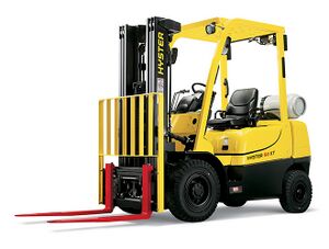
The "carriage" on a forklift is the part that the forks are held by. The carriage is held up by chains that ride on a pulley on top of the lifting cylinder. The carriage is suspended in air by the lifting chains, and held vertical by the rollers on the carriage that slide up and down inside the channel in the mast. As the forklift drives over a bump, the upwards momentum of the truck will cause the carriage to lift up while the lifting cylinder does not, causing slack in the lifting chains. When the carriage falls back down, it is in free fall until all the slack in the chain is taken and the carriage is stopped abruptly by the tension in the lifting chain. To add to that, the forks are not rigidly attached to the carriage so that the width can be adjusted manually for different loads. When the forks bounce up and down on the carriage, it creates a loud, undesirable clanging sound. Hyster-Yale would like to offer a system on their forklifts as a premium option to reduce the bouncing of the carriage. We will be developing a fully-functional concept prototype that aims to reduce or totally eliminate the bounce in the carriage and the forks.
Deliverables[edit | edit source]
A fully functional prototype has been developed, manufactured, and will be returned to be installed on a forklift and tested.
Specifications[edit | edit source]
User Interface Requirements[edit | edit source]
There will be little to no user input required in the final design. Ideally, the mechanism will auto-activate whenever there is not an up or down command from the user controls. A disengage function should be incorporated so that the user can disengage the mechanism from the cab of the forklift.
Load Capacity[edit | edit source]
The mechanism should be able to meet the load capacity of the forklift it will be applied to. Since the goal is a scalable design, the load capacity should meet or exceed that of the parent forklift. The prototype that is being built will be mounted to a forklift with a 2.5 ton capacity.
Surface Types[edit | edit source]
The carriage damping mechanism should be effective in conditions such as bumpy gravel lots, potholes in asphalt and concrete, and a messy concrete warehouse setting.
Design Considerations[edit | edit source]
Hydraulic Power[edit | edit source]
If a hydraulically powered solution is pursued, there are a couple of limitations. Hydraulic pressure is limited to 2500psi working pressure. The pressure and flow rate requirement of hydraulics must not limit the abilities of other hydraulic functions on the truck. Ideally, the solution should share hydraulic power and hoses with what currently exists on the mast and carriage of the forklift. There are a limited amount of hoses that can be routed to the carriage. If separate hoses are required for the mechanism, it will limit the number of other attachments that can be implemented on the forklift.
Electrical Power[edit | edit source]
The forklift runs on a 12 Volt system. Currently, power that is routed to the carriage and mast of the forklift is limited to a headlight circuit. Electrical power faces similar complications with cable routing that hydraulic power faces. Electrical wires routed to the carriage must be able to withstand incredibly high cycle counts before fatigue. Small current draw items such as solenoids can be incorporated, while large current draw items such as motors will require more in-depth project learning.
Safety[edit | edit source]
Safety is a huge consideration in the design stage. Any components within the load line of the carriage must adhere to a factor of safety of 4. High hydraulic pressure also has the capability of breaking skin and causing fatal hydraulic injection into the bloodstream. Any hydraulic power that is implemented must be done so in a way that the operator is out of harms way in the case that a hydraulic line fails and begins spraying high-pressure oil.
Project Learning[edit | edit source]
A few approaches were considered to dampen the bounce of the carriage. Hydraulic Accumulators, Spring/Damping systems, fork clamping mechanisms, and brakes were all researched.
Hydraulic Accumulators[edit | edit source]
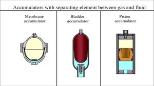
Hydraulic Accumulators work as a hydraulic approach to a spring-/damper system. Pressurized hydraulic and either a pressurized gas or a spring are separated by a membrane. As Hydraulic pressure increases and the volume on the hydraulic side of the accumulator increases, the pressure exerted by the pressurized gas/spring increases, acting very similar to a spring. Accumulators are connected in parallel with the lift cylinder hydraulic circuit. Hydraulic accumulators are commonplace on forklifts with heavy attachments, such as rotators. This application is limited in its damping abilities, and are used to reduce high-impulse loads exerted on the system by a heavy empty carriage bouncing. In order to approach a solution with this route, a hydraulic accumulator would need to be developed from scratch and tuned for the weight of the empty carriage while not limiting effectiveness of the lift system on a fully loaded carriage.
Spring/Dampener System[edit | edit source]
A spring and dampener system could prove an effective approach to eliminating the bounce of the carriage. Springs and dampeners have been explored in two locations on the forklift: on the top of the lift cylinder, and in series with the lift chains. The main design consideration with this approach is that the mechanism will lie directly in the load-line of the lifting system, and must adhere to the high factor of safety requirements for any component within the lifting system. Difficulty with this approach is presented when tuning the effective spring rate and damping ratios. The weight range of the carriage can vary from a few hundred pounds up to 2 or 3 tons. Developing a spring and dampener that is effective with an empty carriage and does not affect the capabilities of a fully loaded forklift brings many challenges.
Force Measurement[edit | edit source]
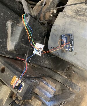
In order to determine whether a design will work or not, quantitative measurement of the problem is required. In order to do this, accelerometers were used to measure the loads present. One accelerometer was attached to the carriage, and one was attached to the mast. The accelerations were subtracted from each other, and the resulting acceleration value was used to develop a plot showing the loads present.
Accelerometers provided valuable information at the beginning of the project, but include a number of limitations. The accelerometer signals were noisy due to random vibrations throughout the truck. Accelerometers do not perform well when collisions are at play, which is exactly what was being tested. In order to be certain that the data was accurate and reliable, the experiment needed to be continued.
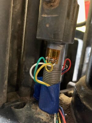
After discussing the data with the client, it was recommended we continue the force measurement with a more accurate strain gauge experiment. The strain gauges were ordered in early December to allow a few weeks of testing before the data was needed to finalize the design. The equipment for the strain gauge experiment took nearly three months to arrive. At this point, it was too late for the data to be used in the design process.
Validation[edit | edit source]
In order to validate our design, we will be building a fully functional prototype. Hyster-Yale has sent us a forklift carriage that we will be installing our completed design on. Once our work is done, the carriage will be sent back to Hyster in Portland to be installed on a functional forklift and operated on their test tracks.
Team Members[edit | edit source]
|
Name: Bryce Bilderback |
Name: Sean Blatner | ||
|
Name: Conner Krezman |
Name: Nick Daquila |


