Marching Band Mobile Platform (The Bandmobile)
| [[File:|300px|center|alt=]] | |
| Sponsors | The University of Idaho |
| Team Name | Bandmobile |
| Duration | Fall 2020 - Spring 2021 |
| Faculty Adviser | Dr. Steven Beyerlein |
| Mentors |
|
| Client | |
| Team Members |
|
The Vandal Marching Band is well-known for their rousing halftime shows that bolster school spirit and provide memorable entertainment at sporting events as well as other activities. This project continues a multi-year collaboration with the College of Engineering in creating awe-inspiring technological platforms and innovations that add an extra level of intrigue to their performances. This year’s updates include four independent omni-wheels with next-generation lithium battery energy storage and robust power electronics/controls. The final platform should be easily reconfigurable for multiple instrument and lighting set-ups.
Problem Definition[edit | edit source]
Background[edit | edit source]
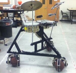
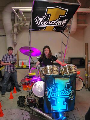
Previous iterations of this project include the following:
| Project Name and Page | Novel Elements | Year | Photo |
|---|---|---|---|
| Band-Beesten rolling drum set |
|
Summer 2013 - Fall 2013 | |
| Band-Beesten 2014 |
|
Fall 2013 - Spring 2014 | |
| BandBeesten Robotic Drumset |
|
Summer 2014 - Fall 2014 | |
| Bandbeesten Legacy |
|
Fall 2015 - Spring 2016 | |
| Bandbeesten: The Legacy Continues |
|
Summer 2016 - Fall 2016 | |
| Bandbeesten: The Legacy Goes On |
|
Summer 2017 - Fall 2017 | |
| UI Marching Band Mobility Platform |
|
Summer 2019 - Fall 2019 | |
| Band on the Run |
|
Spring 2020 - Fall 2020 |
Specifications[edit | edit source]
- Safely move (rotate and translate) a variety of performers and their instruments
- Carry a weight of 300-400 lbs
- Gearboxes encompass 8.3 to 1 gear reduction at motor speed of ~3000 rpm
- 6’ x 6’ footprint, on four wheel assemblies
- Motors controlled remotely
- Add visibility via lighting
Final Design[edit | edit source]
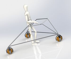
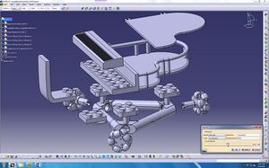
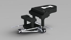
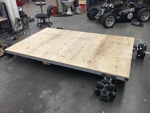
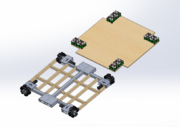
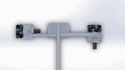
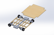
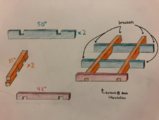
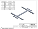
Our updated design can be seen below. It features an aluminum I-shaped frame connecting four omni-wheels, which each have a unique battery and control system. The frame is supplemented by 2x4 members and topped with plywood to create a versatile mounting surface for instruments.
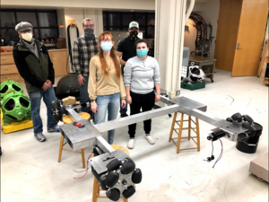
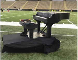
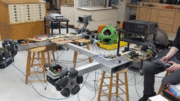
We have manufactured and assembled the majority of the platform, as can be seen in the Implementation column below. We are in the final manufacturing stages for the battery box, the transporting dollies, the wooden deck, and the performance lighting strips.
| Solidworks Design | Implementation |
|---|---|
Subsystems[edit | edit source]
Drivetrain[edit | edit source]
Overview
The drivetrain system connects the wheel subassembly to the frame and allows the platform to move.
Deliverables
The drivetrain subsystem must allow movement to the wheels which moves the platform in a safe manner. It must also be properly secured to the frame to allow said movement.
Requirements
- Reduction ratio of 8.3:1 for the gear motor subassembly
Development
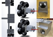
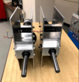
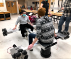
We adopted parts from the previous year’s team. These parts included the wheel subassembly and gear motors. Thr drivetrain subsystem has not changed since last year’s team had it, but we did have to change things to fit our new platform design. Bearing blocks needed to be remanufactured to fit the new platform and gear motor mounts were manufactured to fasten the motor to the gusset plates of the frame.
Current Status
The assembly has been completed and was delivered to the ECE team for circuit testing.
Validation
Completed tests:
- Motor operates properly with minimal noise
- Wheels are able to move freely within the assembly
- Couplers are allowing clear signal from motor to encoder
Planned tests:
- Performing a 360 degree turn in place
- Operating under load for 10 minutes
Photos
Lighting[edit | edit source]
Overview
The lighting subsystem involves LEDs which can be mounted to the platform frame or to instruments in a variety of ways, in order to draw attention to the entire platform during shows. It also involves a microcontroller that will be controlling the LEDs and will be remote-operable.
Deliverables
The Marching Band will have an easy-to-use, flexible lighting system. Limited technical skills should be required to operate, troubleshoot, or adjust the system. This lighting will make the platform visible at any point in the Kibbie Dome, will be remote-controlled, and will be operable for the duration of the Marching Band’s performances.
Requirements
- Easily visible from any location in the Kibbie Dome stands
- Easy to use
- Able to mount to rim of platform or to instruments
- Remotely controllable with primary RC transmitter
Development
The development of this year’s lighting system has been informed by Dr. Bob Rinker and Grae Foster for initial design, the Spring-Summer ECE team for final electrical design, and Ms. Chelsey Lewallen for physical mounting.
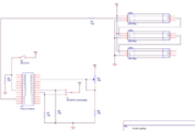
We selected Adafruit NeoPixels as the LEDs, as they are individually addressable and work well with our microprocessor, the Adafruit Feather. These--in addition to the Tenergy battery and other electrical components--will be attached in sets of 3 1-meter strips to a fabric panel. The panel has grommets along the rim for simple connection to the sides of the platform.
We designed three example light shows, and created functions to allow easy future addition of new shows. The shows and LED brightness are controlled by the same remote as the overall platform.
Current Status
The current design involves a set of four one-meter light strips, each of which has its own battery pack, microcontroller, and transceiver. The user can remotely switch between a set of light shows and adjust brightness, which affects all four strips simultaneously.
Validation
- Completed: battery output and charging
- Completed: visible brightness in Kibbie Dome
- Completed: power and current required and supplied
- Planned: run Arduino code for multiple light shows
- Planned: electrical circuit function (battery, Feather, transceivers, and lights)
Photos
Frame[edit | edit source]
Overview
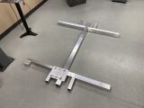
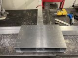
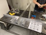
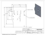
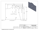
The frame serves as the platform’s light and strong skeleton. It is also where the platform decking is mounted. The longest member of the frame serves as a torsional bar allowing the frame to flex, permitting all wheels to contact the ground. The wheel assemblies are mounted to the frame using gusset plates as well.
Deliverables
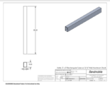
The aluminum members are joined using gusset plates and pop rivets. The wooden supporting frame and deck is joined using riveted brackets (to connect to the aluminum frame) and screws. The frame should be flexible enough to allow for the wheel assemblies to touch the ground but strong enough for the support and movement of the performers.
Requirements
- Aluminum skeleton of the entire assembly, joined by rivets
- 5’ x 6’ decking
- Provide members that the wheel assembly can be mounted to
- Light, strong, and be transported in a reasonable manner
- Allow for all wheel assemblies to contact the ground
- The frame must support a load of 300-400 lbs
Development
The platform was originally designed with the intention of using U-channel members. After the initial design review, it was decided that using square tubing would be preferable. Aluminum tubing was chosen for its light and strong properties. The members would also allow for fast and easy assembly. The tubing was originally designed to be welded together, but the decision to rivet was made. Gusset plates were then designed to hold all members together. Finally, the wooden supporting frame was added.
Current Status
The aluminum frame has been completed and the wheel assemblies have been mounted to the frame. The wooden frame and deck are nearly complete.
Validation
Completed tests:
- Wheel assemblies touch the ground
- Platform height should not exceed 4.5”
- Jointed members should all be in correct location
Planned tests:
- Frame rotates and translates in a proper manner
- Frame supports a load of 3300-400 lbs
Photos
- Wooden Supporting Frame & Deck
- Solidworks Files
Transportation[edit | edit source]
Overview
Two dollies are used to transport the marching band platform to and from the Kibbie Dome for half-time performances.
Deliverables
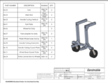
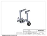
Each dolly must have two swiveled wheels and a wide wheel base to prevent tipping. Each must be ergonomically comfortable to use when transporting the platform. A dolly consists of two wheels and two hinged forks that can be inserted into the platform slots located on two sides of the platform. Two people are required to move the platform.
Requirements
- Able to hold 250lbs each
- Lever arm should be long enough to lift the platform while still considering ergonomics
- Steel rods and pins for increased strength at high stress points
- Locked, upright positioning to safely transport the platform
Development
- ~4ft tall design to reduce force needed to lift platform and has an 8in clearance when platform is lifted
- Handle tubing in two pieces that are connected by a bracket allowing the handle to be adjusted to waist height for easy transport once the platform is lifted
- Handle tubing permanently in an “L” shape for easy transport while still maintaining a lever arm that does not require more than 130lbs of force to lift the platform when platform is fully loaded
- Reduce to 4in clearance to increase lever arm for easier lifting of the platform
- Wider wheel base to prevent tipping when platform is being transported and increased support using gusset plates connecting the handle tubing to the wheel base tubing
Current Status
The current design has two swiveled wheels with a 36 inch wheel base, hinged forks, a height of approximately 41 inches when locked upright, and an “L” shaped handle for ease of transport. See models below.
Validation
A load test will be done using the platform once the dollies are built.
Photos
- Solidworks Files
Battery Box[edit | edit source]
Overview
The battery box is the containment device for the power of the platform. It holds each battery cell in place to ensure that all the batteries are in contact with one another, which will create a steady voltage and battery stress across all cells resulting in a constant power supply.
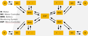
The battery directly interacts with the Battery Monitoring System (BMS), but it also influences the entire platform's functionality. The battery is controlled by the BMS, and power runs to the motor controller and motor; at the same time, the battery provides power for the BMS and microcontroller. Physically the four battery boxes are located on the top of the platform.
Deliverables
The battery box holds each battery pack--made up of eight cells--in place, so they are not knocked around and damaged. It will have to be compact--around 1 cubic foot--and one box will be located at each corner of the platform. The batteries will be contained by a compression fit due to reasons explained later. The whole box must be functional as well as aesthetic as it will be on the deck and visible.
Requirements
- Hold each battery pack tightly for constant connection and safety
- Airflow around batteries
- Box must be a cubic foot in size
- Hold 8 batteries in parallel and 8 in series
Development
We were planning to use completely new batteries--selected by the Spring-Fall electrical team--so the containment device had to be completely different as well. We were originally going to be spot welding all the batteries which would make a nice compact block (Version 1, below).
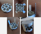
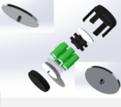
This idea was thrown out the window when the team building the battery realized that the spot welder that they bought could not actually spot weld the material being used. This called for a compression fit, which is considered inferior. Thus, in the second iteration, we created individual cylindrical tubes that attached each group of cells in parallel to account for the Amp-hours (Ah) needed. Then each cylindrical block would be connected in series to get to the desired voltage. Prototypes were made (Versions 2-4), but during the finalization process we realized it was much too big and expensive to continue.
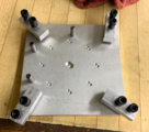
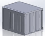
We ended with the design similar to the 4th iteration, but much different as well. The battery box is composed of 8 battery packs, each which hold 8 battery cells. Each cell pack is contained with (2) square caps which sandwich the cells in place, we have some copper conducting plates on each side, with springs underneath one side to ensure each battery has the same load and stress. The battery packs are oriented in a large rectangle, and then an acrylic covering is placed around it with an aluminum plate on top to mount the BMS unit, the motor controller, and some large resistors.
Current Status
As it stands the battery box is in development, we are in the process of machining the caps and just finished machining all of the copper conductor plates. Once those are machined we will turn to building the battery pack containment box, which is being finalized now. Once all that is machined, it will be a matter of assembling it, and testing.
Validation
The ECE team was able to perform a basic test on the controller by using their improvised battery cell to make sure the controls work. We also did some initial prototype testing to make sure the cylindrical cell holder would contain the batteries snuggly, which they did. When the 3D modeled battery pack was placed onto the 3D modeled platform we realized how big they really were which resulted in a decision to try something new.
Photos
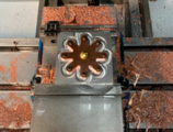
- Manufacturing Components
- Development Versions
Documentation[edit | edit source]
Drawing Package[edit | edit source]
Please find our drawing package (updated 17 December 2020) below:
File:01-00 Platform Assembly-merged.pdf
Project Schedule[edit | edit source]
Please find our live Gantt Chart here.
Design Validation[edit | edit source]
Please find our live Validation Plan here.
Budget[edit | edit source]
Please find our live Budget here.
Minutes[edit | edit source]
Please find our meeting minutes (updated 8 December 2020) below:
File:Capstone Meeting minutes.pdf
Presentations[edit | edit source]
Snapshot 3 (09-03-2021 16:30)
Engineering Release Review (26-02-2021 12:30)
Snapshot 2 (04-12-2020 08:30)
Design Review 1 (10-11-2020 08:30)
Snapshot 1 (13-10-2020 15:30)
Team Members[edit | edit source]
| Annika Esau
Major: Computer Science, Psychology |
Jacob Thorngate
Major: Mechanical Engineering | ||
| Ben Randall
Major: Mechanical Engineering |
Kaitlin Tabaracci
Major: Mechanical Engineering | ||
| Cole Brusven
Major: Mechanical Engineering |
Zachary Laymon
Major: Mechanical Engineering |
