Seasonal Free Cooling for University Data Center
| Sponsor | |
| Team Name | Free Breeze Brothers |
| Duration | Summer - Fall 2017 |
| Faculty Adviser | Dr. Steve Beyerlein |
| Client | Scott Smith |
| Team Members |
|
The design and implementation of a free cooling system to chill water for the UI campus, during the winter months, is the main goal of this project. By considering system economics, environmental impact, and overall optimization, among other factors, the designed system will provide an efficient, cost-saving method of cooling water through the use of cold ambient air.
Problem Definition[edit | edit source]
Currently, to chill water for campus, the University uses vapor-compression chillers throughout the entire year. While this process is able to handle the load, this type of system experiences problems during the winter time. The main issue is with the evaporative cooling towers, which are prone to ice build-up. The reason for this is that the cooling water is directly exposed to the freezing conditions. When this build-up happens, damage may occur to the system, so ice must be manually removed from the cooling towers. There are a few methods for ice removal, but none of them are very efficient and all require human intervention into an otherwise automated system. Other than freezing, which interrupts system operation and is hard on equipment, other issues include working fluids freezing within pipes and flash freezing of humid exhaust air.
Background[edit | edit source]
Free cooling, also known as enterprise cooling, involves utilizing relatively low temperature ambient air to cool a working fluid within a system. Conversely, a conventional method for completing the same task would be to use a vapor-compression chiller. However, free cooling is enticing for a few reasons. First, air is a working fluid within the system that does not have an associated monetary cost, hence the name "free" cooling. Secondly, operational costs for a free cooling system are generally lower, due to the fact that pumps and fans are the only main components that must be powered. In a conventional system, compressors and cooling towers, along with pumps, produce a much higher power demand while operating. Finally, a free cooling system can be a completely enclosed system, protecting it from the environment and eliminating the need for make-up water and continuous chemical treatment of the system.
Deliverables[edit | edit source]
For this project, the final product will be a complete design and analysis, with supporting calculations, of a free cooling system to chill water for the UI campus during the winter season. Included in this design will be justifications of all design decisions, along with a collection of simple if-then statements for the end user of our system to follow during operation. Once our design has been approved, the University will purchase and install the components outlined in our design to create a full scale, operational free cooling system.
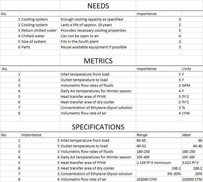
Specifications[edit | edit source]
Project Design[edit | edit source]
The following information provides evidence and reasoning for the decisions that we made during the design of our system. Additionally, both of the designs that we produced for the system are presented.
System Modeling[edit | edit source]
Above is a comparison of two potential heat exchangers for use in our system, along with a table of important values from a hypothetical test system. Shown below is a graph of system cooling capacity versus ambient air dry bulb temperature.
Off the Shelf Design[edit | edit source]
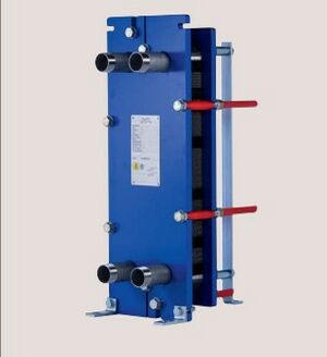
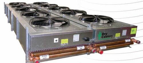
For this design, we decided to use completely new parts and components throughout the system. This design is also a representation of a worst case scenario that provides a maximum for the total cost if we decide to construct the entire system from scratch. The following pictures are of some of the new components that have been selected for this design.
Repurposed Design[edit | edit source]
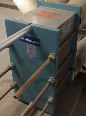
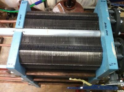
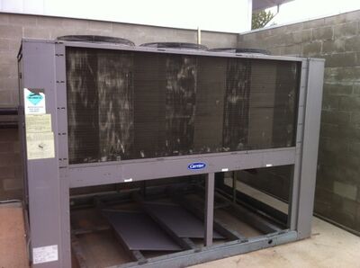
This design involves the integration of components owned by the University that we are able to repurpose for use within our system. By salvaging these old units, we will save a large sum of money over a new purchase. The two main components that will be reused in this design are the plate and frame heat exchanger and the dry cooler, which happen to be the most expensive components to buy new. Pictures of the recycled components of this design are shown below.
It is important to note that, for the designs above, pumps, valves, and piping will have to be purchased. Also, pipe size and pump sizes are exactly the same for both.
Final Design[edit | edit source]
The following information provides justification for design choices and finalized schematics for our system.
| Decision | Selection | Justification |
|---|---|---|
| Conventional Cooling Tower vs Dry Cooler | Dry Cooler | The dry cooler meets all of the specifications for this project. These include: 1) Keeping the coolant from freezing. 2) Keeping the coolant from being exposed to the environment. 3) Utilizes cold ambient air or “Free Cooling” to chill coolant instead of refrigeration cycle. |
| Shell and Tube vs Plate and Frame Heat Exchanger | Plate and Frame | The plate and frame heat exchanger is a much better fit for our project due to its efficiency, space requirement, and ability to be easily modified, by adding or removing plates, for different cooling loads. Also, it is much easier to clean and maintain opposed to a shell and tube. |
| Conventional Pump vs VFD Pump for Coolant Loop | VFD Pump | Due to the fact that our systems uses ambient air, which has a large temperature range, our system will require a VFD pump to vary the flow through the coolant loop i.e. less flow when ambient temps are lower and more flow when ambient temps are higher. |
| Water vs Ethylene Glycol in Coolant Loop | Ethylene Glycol | Since our system will be operating in sub-freezing temperatures, it is important that our coolant fluid does not freeze. An ethylene glycol solution has a lower freezing point than water, so this added safety factor against freezing makes sense for our system. |
| Free vs Forced Convection in Dry Cooler | Forced Convection | Based on our calculations, forced convention is much more feasible for the system. With free convection, the size of dry cooler necessary is very large and expensive. Additionally, forced convection gives us much greater control of system efficiency and performance. |
| Top vs Bottom Mounting of Dry Cooler Fans | Top Mounting | For our system, it makes more sense to have the bottom side of the heat exchanger open and have the fans draw air through the system. All we will have to add is a method for protecting the fans from ice and snow. Lastly, most manufacturers produce the dry coolers with top mounted fans, and it would likely be an added cost, if even possible, for underside mounting of the fans. |
| New PFHX vs Repurposing Old PFHX | Repurpose Old PFHX | Because we have access to a PFHX in good condition that we can reuse, it was a simple decision to go this route instead of buying new. |
| New Dry Cooler vs Repurposing Old Dry Cooler | Repurpose Old Dry Cooler | The university already owns a dated dry cooler that has been put out of service. However, by repurposing components from this piece of equipment, we can recycle it into a functioning dry cooler that will be proficient for our system. This way, we save the cost of purchasing a new dry cooler and salvage an otherwise abandoned component. |
Below are two schematics of our system, the first being a general system outline that shows all of the main components and the second being a floor plan of the actual installation location with options for placement of our system.
Project Implementation[edit | edit source]
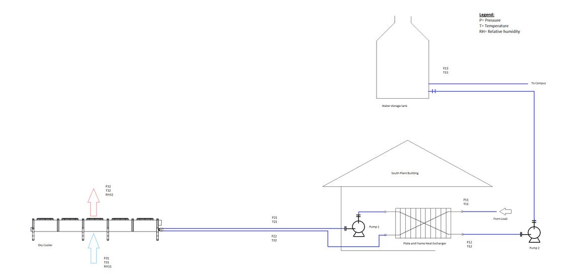
The information presented in this section pertains to the construction and overall completion of our system. Shown below is the Piping and Instrumentation Diagram (P&ID) for our system. The purpose of the diagram is to show the location and type of each sensor that needs to be installed in our system.
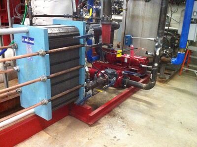
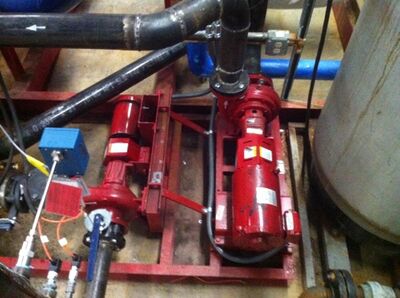
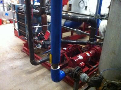
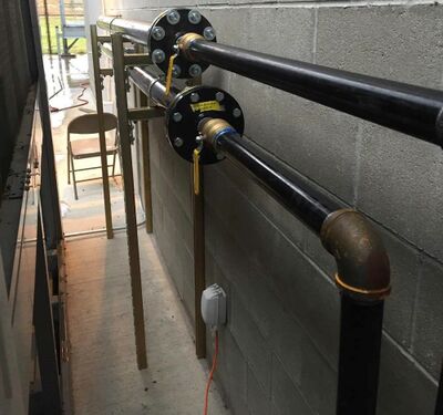
The table below displays photos of the actual system that was installed on the UIdaho campus using our design.
Team Members[edit | edit source]
| Name | Discipline | |
|---|---|---|

|
Kevin Marwan | ME |

|
Justin Hinrichs | ME |

|
Alex Leppek | ME |

|
Frank Guo | ME |
