Code Generation (MakerBot)
Main Article: 3D Printing
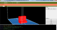
Code generation is done in ReplicatorG software. ReplicatorG converts the STL file into a build plan for Makerbot based on the selected settings. Various changes to the parts orientation, size, and build quality can be adjusted in ReplicatorG.
For a good print a part must be placed in ReplicatorG for code generation. The part must be oriented so the side with the most surface area is on the plate. Other special conditions exist and are mentioned in Part Orientation. ReplicatorG will hollow out the part, build internal support structures, and slice the part into layers based on the "Generate Gcode" . After Gcode is generated the part can be exported to the SD card to be built by MakerBot.
Exporting Part to STL[edit | edit source]
Prerequisites[edit | edit source]
Before a part can be exported as an STL to be printed it must meet the geometric constraints of the MakerBot. See Part Design for information on geometric constraints and common errors.
File Naming limitations[edit | edit source]
The file name cannot exceed more than 26 characters (not including the file extension). All valid file name characters should be accepted, but may be the problem if the file does not show up on Makerbot when the file is transferred.
STL File[edit | edit source]
STL is a generic 3D file type and can be produced by most 3D based programs. Instead of having the steps to create the part, a stl file contains only the geometric surface dimensions.
Because a stl file contains only the geometric surface dimensions it is important to also save the part as the typical SLDPRT. This enables a user to go back to the Solidworks file and make changes to the parts design if required.
Exporting STL from SolidWorks[edit | edit source]
- Verify the part meets the geometric constraints of Makerbot.
- Save Part as typical “SLDPRT”
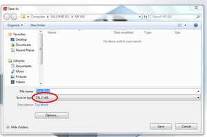
- Select “Save As”
- Choose Destination
- Change Save As Type to "STL(*.stl)"
- Click “Save”
Steps for Generating Code[edit | edit source]
- Run Replicator G
- Open Part
- Orient Part and Scale
- Select "Generate Code"
- Apply Options
- Hit “OK” on Acceleration Warning
- After GCode is made select “Build to File for use with SD Card”
- Select Save location
- Change "Save As"
ReplicatorG Installation[edit | edit source]
Code generation is done in ReplicatorG. It can be downloaded here. Version 0040 is currently recommended. It will also require Python v2.7.5 to run properly. It is available here. ReplicatorG and Python will run on Windows, Mac, and Linux.
Load Part[edit | edit source]
Once ReplicatorG is running, parts can be loaded from the file menu. Only STL files are usable by ReplicatorG.
Part Orientation[edit | edit source]
Parts in RelpicatorG must be placed flat on the platform. The side with maximum surface area should be facing the platform. Moving, rotating, and scale are done to achieve this.
Move[edit | edit source]
Opened parts can be moved by using the “Move” button on the left. This allows for the part to be moved by use of the buttons on the right side or by clicking and moving the cursor. It is best practice to place the part in the center of base plate (or as close to the center as possible). The “Center” button will typically center the part.
Rotate[edit | edit source]
Opened parts can be rotated by using the “Rotate” button on the left. This allows for the part to be rotated in 90° increments by use of the buttons on the right side or by clicking and moving the cursor. Clicking and moving the cursor is tricky and not recommended.
If the part is oriented at an angle, lay flat can be selected to place the part securely on the table. Lay flat will automatically lay the part down on the table using the nearest flat surface.
Scale[edit | edit source]
Opened parts can be scaled by using the “Scale” button on the left. Parts will scale relative to current size. If it has been scaled once, the second scale will be based of the new scaled part.
For example: If a 1" part is scaled by 0.5 the result is a 0.5" part. If the part is scaled again by 0.5 the result is a 0.25" part. If, after the previous scaling, it is required the part be 1/5 the original, it must be scaled up by 2 and then down by 0.2.
Slicing Settings[edit | edit source]
Supports[edit | edit source]
Supports are plastic pieces placed strategically throughout parts that have overhangs and arches to prevent the plastic from drooping when plastic layers are being placed. Only supports if absolutely necessary because it increases build time and leaves marks where the supports were attached.
Supports can be added by ticking "Use Raft/Support" and selecting a value in the "Use support material" dropdown.
Rafts[edit | edit source]
A raft lays down a thin pattern of plastic for the part to be built on. Rafts are used to make removing the part from plate easier, to prevent warping, and to increase parts sticking together. Rafts should not be used if part is circular because the part will fail. Removing rafts can be difficult so they should only be used if necessary.
Object infill (%)[edit | edit source]
This changes the percentage of internal fill in the part. The standard 10% will suffice for most parts and is fairly strong. If extra strength is needed this can be raised. Do not raise this too high - prints will begin to take much longer, you will use much more material (which costs money), and there is a chance that you could cause the nozzle to jam.
Layer Height[edit | edit source]
Layer Height changes the thickness of layers. Decreasing layer height will increase the number of layers and increase build time. It will also result in a more accurate piece. Decreasing layer height can remove build errors such as: jagged arches, sagging arches, and rough fillets. It is recommended that .27mm be used for standard builds and .1mm to .15mm be used for builds that could be problematic. The minimum layer height of MakerBot is .1mm.
Number of Shells[edit | edit source]

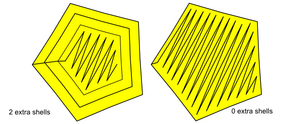
This setting lets you change the number of outer shells that the printer creates before starting infill. Changing the number of shells is necessary when a thicker outer wall is needed for Post Print Processing. The default value of 1 fine for most builds. Each shell will be as thick as the filament is, so consider this when deciding how many shells you want for your part.
Feedrate (mm/s)[edit | edit source]
Set feedrate to 70. This will always be the same.
Travel Feedrate[edit | edit source]
Set travel feedrate to 150. This will always be the same
Print Temperature[edit | edit source]
Set print temperature to 230°C. This will always be the same.

